The F-15 ASAT story
By Gregory Karambelas, edited
by Sven Grahn
[Gregory Karambelas' text has
normal font, Sven Grahn's text is in italics]
Note: Orbital analysis presented
at this web page was generated using Two-Line Element sets obtained from
the NASA OIG web service and not the newer Space-Track site.
 I
am an ex Air Force Captain. My first four-year assignment was on
the F-15 ASAT test program! I was stationed at Vandenberg Air Force
Base and had several responsibilities including being an analyst for both
the Miniature Vehicle (MV) interceptor made by LTV (Vought) and for the
Instrumented Target Vehicle (ITV) made by the AVCO corporation. I
made several trips to the factories of both companies and saw up close
and touched these vehicles many times. I was intimately familiar
with their design, construction, and operation. These are my brief recollections
I
am an ex Air Force Captain. My first four-year assignment was on
the F-15 ASAT test program! I was stationed at Vandenberg Air Force
Base and had several responsibilities including being an analyst for both
the Miniature Vehicle (MV) interceptor made by LTV (Vought) and for the
Instrumented Target Vehicle (ITV) made by the AVCO corporation. I
made several trips to the factories of both companies and saw up close
and touched these vehicles many times. I was intimately familiar
with their design, construction, and operation. These are my brief recollections
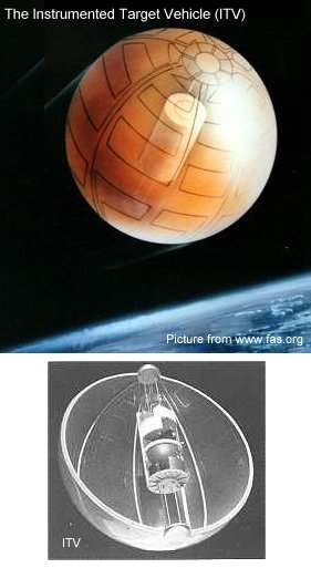
Target vehicle
In short, the ITV balloon, had
a grid of break-wires on the surface. In case the interceptor did
hit the ITV, we would be able to tell where on the surface we hit it.
The ITV was sending telemetry in real time once it was inflated on the
final orbital pass. We were guaranteed a few frames of data before
the vehicle was destroyed. The ITV had magnetometers on board to use in
determining the attitude of the ITV. This allowed us to know with
very good precision the location of the Hit Position Indicator wires and
the IR signature in the field of view of the interceptor.
In case the interceptor did
not impact the ITV, the ITV was equipped with a Miss Distance Indicator
(MDI). This was a continuous wave radar transceiver. It sent
out a continuous signal, and received the doppler shifted returns from
anything that flew by it. It did not have very long range, but it
would give us a very accurate estimate of the scalar miss distance.
I remember having a few good technical papers at the time detailing how
we reduced the data. Those CW MIDIs are fairly standard. One
just looks for the change in the slope of the doppler returned frequency
and you know when the closest approach was. I think a few iterations
and analysis of the slope and rate of change of the frequency is needed
too, but the process was fairly straightforward. Xontec incorporated,
a well-known company specialized in Test Range tracking and Best Estimate
Trajectory analysis did the calculations for us. But of course we
did not shoot at the ITVs so all we had is one run of simulated data that
I believe AVCO had generated against a howitzer cannon rail test shot.
The ITV Miss Distance Indicator
was not high power and was basically omnidirectional. It was designed
to help out post test analysis of flights where we got close, inside the
tracking resolution of the ground based tracking radars, but missed.
The range tracking radars at the time could only reconstruct the trajectory
and distances with an accuracy of 20-50 feet, depending on whose Best Estimate
of Trajectory (BET) analysis you believed. So the Miss Distance Indicator
was designed only to operate inside that range. If we missed by more
than 100 feet, the range radars would certainly tell us that. I can't
recall the frequencies that RF Miss Distance Indicator used. That
was not important to my analysis so it is not coming to mind.
I assume it was not in the same frequency band as the test range C-band
tracking transponder radars to avoid signal interference.
 Obviously,
if we hit the ITV, we knew the trajectories coincided to within 6 feet,
the diameter of the balloon. I remember seeing the canisters
on the lab bench and the kevlar laying around. I calculated that
infrared signature so many times getting ready for the actual intercept.
I should remember that number as I needed the cross section area exposed
to the interceptor!
Obviously,
if we hit the ITV, we knew the trajectories coincided to within 6 feet,
the diameter of the balloon. I remember seeing the canisters
on the lab bench and the kevlar laying around. I calculated that
infrared signature so many times getting ready for the actual intercept.
I should remember that number as I needed the cross section area exposed
to the interceptor!
Those wires on the surface
would tell us where on the ITV we hit or the Miss Distance Vector.
That was helpful for the guidance analysis of the interceptor. When
one is trying for a hit-to-kill, 3 feet or a 1 foot miss distance is important,
and the location on the balloon was supposed to help the terminal guidance
people figure out exactly what the interceptor did.
Yes, we used to joke about
the ITV's Miss Distance Indicator being used as a proximity fuse, especially
when we heard that the test data tape of one howitzer shot from a test
range was used to check out the Miss Distance Indicator. But it was
not used as a proximity fuse, just a closest approach determiner.
The ITV was "inflated".
It had a hydrazine catalyst generator that produced hot gases from a rheuthenium
catalyst decomposition driven device. It was designed to heat and
maintain the Kevlar balloon at a temperature that would emit the desired
infrared signature in a controlled manner for our Interceptor to see.
Post test telemetry analysis was used to calculate the IR signature of
the balloon. There were many temperature sensors embedded in the
kevlar in known locations.
Homing vehicle
guidance
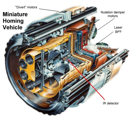
One must remember that the Miniature
Vehicle interceptor had no "guidance" as most people think. It had a ring
laser gyroscope for spin rate determination, and for creating its own reference
before it left the missile upper stage, but it had no gyroscope in the
normal sense. It did not know its own altitude, or attitude.
All it knew was the position of IR targets in its own field of view.
It tried to home in on that. It had no idea of the range to
target, it's altitude, etc. It had a C-band transponder
for radar tracking. The interceptor was developed from an old US Army program
that was tested against tanks! I remember seeing some photos of it.
The interceptor was called
the Miniature Vehicle (MV) It was spun up to approximately 30 revolutions
per second just prior to being deployed from the Upper Stage. It
did have an infrared sensor on board. This was before the days of
Charge Coupled Device arrays so it had "strip" detectors on it. I
should be able to remember the composition we used. It was
not your usual Mercury Cadmium Telluride. I think it was an Indium
Bismuth strip. Hughes Research Corporation AKA Santa Barbara Research Corporation
was the manufacturer. It had four strips arranged in a square
and four spiral curves. We could determine the object's position
in the focal plane by measuring the time of detections on the strips.
The object detection was by a simple centroid detector as the IR "blob"
crossed the strips. (See figure below)
The guidance of the MV was
simple Direct Proportional Line of Sight. The MV had 56 full charge
solid propellant rockets arranged around the circumference, and 8 half
charge solid rocket motors for a "bang-bang" control system. The
56 motors were called divert motors, and the 8 other ones were supposed
to be used in the end game phase of the intercept where the needed positional
changes would supposedly be less.
To control or dampen coning
or wobbling of the interceptor, the back end of the interceptor had four
pods of attitude control rocket motors. They were little tiny squibs
that would detect the wobbling or off central rotation of the interceptor
by logic that would look at the strip detector data. I can't recall
exactly how many charges were in each pod, but the number was not that
large.
 Sven
Grahn's comments: I have been thinking about the intercept geometry of
the F-15 ASAT. As I see it the two-stage booster could not have reached
more than maybe 4-5 km/s at burnout, which is not enough to catch up with
a satellite in orbit moving at 7-8 km/s. Therefore the intercept must have
been made "head-to-head", i.e a head-on approach. Also, this would have
made it necessary to launch the interceptor more or less into the orbital
plane of the target. Of course the F-15 could fly to a point in the orbital
plane of the target...within certain limits, of course. Also, the trajectory
must have been chosen to make the necessary field-of-view of the IR telescope
reasonably small, i.e. the angle between the interceptor and target trajectories
must have been as small as possible. In this way the target moved little
relative to the intrecptor's flight path vector.. I have tried to sketch
this in the attached picture.
Sven
Grahn's comments: I have been thinking about the intercept geometry of
the F-15 ASAT. As I see it the two-stage booster could not have reached
more than maybe 4-5 km/s at burnout, which is not enough to catch up with
a satellite in orbit moving at 7-8 km/s. Therefore the intercept must have
been made "head-to-head", i.e a head-on approach. Also, this would have
made it necessary to launch the interceptor more or less into the orbital
plane of the target. Of course the F-15 could fly to a point in the orbital
plane of the target...within certain limits, of course. Also, the trajectory
must have been chosen to make the necessary field-of-view of the IR telescope
reasonably small, i.e. the angle between the interceptor and target trajectories
must have been as small as possible. In this way the target moved little
relative to the intrecptor's flight path vector.. I have tried to sketch
this in the attached picture.
Infrared
sensor design
The interceptor had a folded
Gregorian Telescope for an optical system which as you know is similar
to a Cassegrain design. It had a Honeywell ring laser gyro onboard
to maintain an inertial timing reference. We "initialize" this just
prior to deploying the interceptor from the upper stage. This allowed
us to reconstruct the attitude of the interceptor in real space.
But the interceptor really had no idea where it was or how fast it was
going or how far away the target was. It would happily have sat there
and tried to maneuver and null out any Line-Of-Sight changes even if it
was 10,000 miles from the target and moving away from it! It did
not know. If the aircraft/missile did not put the interceptor
in the right general place where it could maneuver to get in the way, no
intercept could possibly occur. I am sure the total divert capability
was classified, and I am not sure I even knew what it was. The solid
rocket divert motors were quite a development problem. To minimize
the IR contaminants and debris, they used some specially designed organic
propellant. Unfortunately, as I recall we had many problems with
voids and propellant slumping. Our IR sensor was so sensitive, I'm
not sure if all the trouble of trying to design special propellants was
worth it. I did a short paper for my Master's degree calculating
the IR signature of those little burned propellant particles and it is
pretty amazing how "bright" they are and how long they stay bright with
radiation being the only means of heat transfer in space.
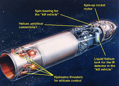
The interceptor detector
was cooled by liquid helium prior to release. Yes, 4 degrees kelvin
helium. We had a large helium dewar on the ground that was about
the size of the Robot on the old Lost in Space TV show. We then had
a large helium dewar on the F-15. We removed the ammunition drum
and the back seat in the F-15 with a large tape recorder and the helium
dewar. This allowed us a fair amount of time to do pre-mission checks,
perform the flight from Edwards AFB to Vandenberg AFB. The upper
stage of the missile also had a helium dewar that obviously was much smaller
than the one on the aircraft. This dewar was connected to the interceptor
by a supply and return line.
 In
space, after the missile was launched, these cryo lines were retracted,
and then two spin motors located on the spin bearing assembly of the interceptor
were fired and the interceptor was spun up. It is important to note
that the interceptor did not work while not spinning. This was not
a staring array. I have attached a crude drawing of the strip detector
layout. Those spiral lines were symmetrical logarithmic spirals (spirals
of archimedes as I recall). Some simple geometry and trigonometry
would enable us by recording the time of the detector crossing, calculate
the objects location in the sensor field of view.
In
space, after the missile was launched, these cryo lines were retracted,
and then two spin motors located on the spin bearing assembly of the interceptor
were fired and the interceptor was spun up. It is important to note
that the interceptor did not work while not spinning. This was not
a staring array. I have attached a crude drawing of the strip detector
layout. Those spiral lines were symmetrical logarithmic spirals (spirals
of archimedes as I recall). Some simple geometry and trigonometry
would enable us by recording the time of the detector crossing, calculate
the objects location in the sensor field of view.
The spin bearing was quite
a development problem too. Once the interceptor was spun up, we did
not have all day to deploy it, and spin-down was a problem as the interceptor
had to operate within a certain revolutions-per-second range. Since
my BS was in mechanical engineering I would stick my nose into those meetings
quite a bit.
Flight operations
I also worked briefly on coordinating
the "Pass Plan" with the Air Force Satellite Control Network headquartered
at what was then called "Sunnyvale Air Force Station" before it was renamed
to Onizuka. The way we planned the engagement shot, how we would contact
the ITV as it passed over Hawaii, "inflated" or "erected" the balloon,
etc. was actually a very tight timeline. We based the ASAT
missile and F-15 at Edwards AFB, but we launched the ASAT missile off the
coast of California. We had to have the ITV up and running and all
heated up as soon as the interceptor was able to see it. There were
many arguments over who should commit first. Do you waste a $100
million dollar interceptor, or do you waste a very expensive ITV that had
to be launched into space many months in advance? Who gives the go,
no-go? The ITV could basically only be used once if it was fully
heated. It did not have a lot of hydrazine on board for heating purposes.
I think we could shut it down and reuse it once again if it was briefly
puffed up and not using much hydrazine for long, but nobody trusted the
corrosive effects of the catalyzed hydrazine gas products once they flowed
all over the balloon and electronics.
Sven Grahn's comments:
The following flight tests were conducted with the system
| Nr |
Date |
Purpose, result |
| 1 |
21 Jan 1984 |
Successful: missile tested
without miniature vehicle |
| 2 |
13 Nov 1984 |
Failed: directed at a star
with miniature vehicle |
| 3 |
13 Sept 1985 |
Successful: destroyed NLR
satellite P78-1 Solwind (79-17A, Sat Cat Nr 11278) |
| 4 |
22 Aug 1986 |
Successful: directed at
a star |
| 5 |
29 Sept 1986 |
Successful: directed at
a star |
 "
....By September 1985, all was finally ready for a test against an orbiting
satellite. On Sept. 13, Maj. Wilbert D. "Doug" Pearson, the director of
the F-15 ASAT CTF, took off on a crucial mission that required him to fly
an extraordinarily exacting profile in order to arrive at a precise firing
location at exactly the right time. Flying at Mach 1.22 some 200 miles
west of Vandenberg Air Force Base, he executed a 3.8g pull-up to a climb
angle of 65 degrees. The missile automatically launched itself at 38,100
ft. Minutes later, orbiting peacefully 345 miles above the Pacific Ocean,
an obsolete satellite named P78-1 was suddenly shattered into pieces. Pearson
had become the world's first pilot ever to shoot down a satellite. To this
day, now Maj. Gen. Doug Pearson remains, as Air Force Materiel Command
Commander Gen. Lester Lyles recently observed, the first and only "space
ace ..." (1)
"
....By September 1985, all was finally ready for a test against an orbiting
satellite. On Sept. 13, Maj. Wilbert D. "Doug" Pearson, the director of
the F-15 ASAT CTF, took off on a crucial mission that required him to fly
an extraordinarily exacting profile in order to arrive at a precise firing
location at exactly the right time. Flying at Mach 1.22 some 200 miles
west of Vandenberg Air Force Base, he executed a 3.8g pull-up to a climb
angle of 65 degrees. The missile automatically launched itself at 38,100
ft. Minutes later, orbiting peacefully 345 miles above the Pacific Ocean,
an obsolete satellite named P78-1 was suddenly shattered into pieces. Pearson
had become the world's first pilot ever to shoot down a satellite. To this
day, now Maj. Gen. Doug Pearson remains, as Air Force Materiel Command
Commander Gen. Lester Lyles recently observed, the first and only "space
ace ..." (1)
President Reagan gave
the go-ahead for the test against a real target in space on 20 August 1985
(4). The test was originally scheduled for
4 September, but because the 15 days notice had not been given to Congress
it was delayed 9 days (3). The target was
Solwind P78-1, a gamma ray spectroscopy satellite weighing 850 kg (2)
that had been launched in February 1979 into an initial orbit at 563-602
km at 97.6 degrees inclination. P78-1 was in a noon-midnight, Sun-synchronous
orbit. The identity of the target was actually leaked before the test (3).
The most probable time
of intercept is at around 2040 UT on 13 Sept. 1985 when the Solwind passed
off the US West Coast from south to north. This time of intercept is also
given in (2). The local time in the
Pacific time zone was then 1240, i.e. the target satellite was illuminated
making the surface of the spacecraft warm and radiating infrared radiation.
The altitude of the target satellite at the probable time of intercept
was 530 km.
Target
vehicles finally launched
Sven Grahn's comments: The
two target vehicles (85-114 A Sat Cat Nr 16328, 85-114 B Sat Cat Nr 16329)
were actually launched on 13 December 1985 at about 0230 UT from Wallops
Island into orbits at 315-772 km and 319-768 km and 37.05 deg inclination.
The mass of each vehicle was 81.6 kg (2).
A Scout rocket was used and it carried both ITV's on top of the final stage.
It is interesting to note the quite elliptical orbit. Was this done on
purpose to be able simulate "adversary" targets at altitudes ranging from
those of photo-reconnaissance satellites to those of other Soviet space
assets such as navigation satellites? However, it also seems that the Scout
launch vehicle underperformed, so the elliptical orbit may be unintentional.
It is interesting to plot
the trajectory of an ITV when passing straight over the ground station
at Hawaii, where Greg Karambelas says the inflation command would be issued.
It turns out that the inclination of the orbit seems to be deliberately
chosen so that the target satellite would head straight for the southern
California coast, indeed directly in the direction of Vandenberg and Edwards
AFB where the F-15 was based (see figure below).
One can also see that
the timeline was tight. After AOS at Hawaii it would take a few minutes
to command and verify that the balloon had deployed properly, say five
minutes. Then there would only be ten minutes before the target vehicle
crossed the California coast. The F-15 would hardly be able to scramble
and reach launch altitude in such a short time.
 What
happened to the target vehicles?
What
happened to the target vehicles?
According to Gregory Karambelas
the target vehicles were battery-powered and were kept dormant and uninflated
in orbit following the ban on further testing of the ASAT system. Finally,
permission was granted to test the inflation system. Evidence of this can
be gathered from an analysis of the orbital period of the taget vehicles.
This analysis shows that the ITV-2 (Sat Cat Nr 16329) target was actually
inflated late on 17 December 1986 or early on 18 December, see figure on
the right. The decay rate of the spacecraft suddenly increases as the cross
section suddenly increases.
No corresponding sudden
increase in decay rate can be observed for the ITV-1 (Sat Cat Nr 16328)
vehicle. The ITV-2 target decayed after 604 days (on 9 Aug 1987) and the
ITV-1 target decayed after 1245 days (on 11 May 1989) (2).
References and
Notes
-
Raymond
L. Puffer, "The
Death of a Satellite"
-
D.G.
King-Hele et al, The RAE Table of Earth Satellites 1957-1989, The Royal
Aerospace Establishment, 1990
-
G.E. Perry,
day-to-day log, entry for 5 Sep 1985.
-
G.E. Perry,
day-to-day log, entry for 21 Aug 1985.

 Back
to Space History Notes
Back
to Space History Notes