Sven Grahn
The early Soyuz craft were equipped with a radio system called IGLA ("Needle") for guiding the active craft to dock with another Soyuz or a Salyut space station. This system provided data that was used for controlling both the relative motion and the attitude of the two approaching craft.
The passive craft was equipped with a radio system that could provide a radio beacon for homing by the active craft or a transponder function for measuring range and range rate. The basic concept of IGLA is described in (1).
Antennas of the IGLA system
On Soyuz and Salyut you can see five types of antennas as shown in the figure below, which shows the antenna location on the active and passive craft in a rendezvous and docking operation.
 |
Antenna type
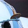
A: This is an omni-directional antenna for transmissions from a passive
spacecraft. It has a cardioid hemispherical pattern. It probably is a conical
helix design. The antenna or its active element is fixed and does not move.
This type of antenna is quite evident in all pictures of early Soyuz and
Salyut spacecraft.
The picture on right shows the conical transmission antenna (A) together with the reception antenna (B) of the other craft (see below). |
 |
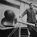 |
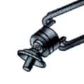
Antenna type B: The
antenna on the left is a reception antenna used on both the active and
passive craft to provide relative orientation information. Inside the outer
shell - or radome - there is probably a rotating antenna element similar
to the rotating feed on an old tracking radar. The active element could
look like the corresponding antenna on modern Soyuz TM craft. (See picture
on the right)
In the left picture we also see cosmonaut Papel Popovich. Interestingly the radome also has an "back shell" that folds out behind it. No such device has been seen on any other such antenna. The rotating antenna pattern probably looked something like the picture on the right. |
 |
 |
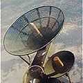
On the active
craft there was a gimbaled dish antenna (left) (type D) that was
used for transmit and receive and which tracked the angular motion of the
passive craft relative to the active craft. The rate of motion of the line-of-sight
between active and passive craft is a measure of the miss distance during
an approach. It is necessary for this antenna to be able to swing 180 degrees
in the plane defined by the axis of the spacecraft and the antenna tower.
The reason is that the spacecraft must be able to aim it main thruster
in the approach direction.
On the passive craft there was a fixed dish (type C) for transmitting ranging signals back to the active craft (see picture on the right). The smaller dish may possibly be used when a wider beam is needed. |
 |
Mutual search and acquisition
At the start of the homing phase the passive craft was rate-controlled in terms of attitude.
Step 1: The passive
craft transmitted a CW beacon signal through its two transmit antennas.
This CW signal was picked up by one of the rotating search reception antennas.
The active craft was slowly rotating to make it possible for one of its
receive antennas to acquire the passive craft. The reception antennas provide
error signals that were used to point the longitudinal axis of the active
craft at the passive craft. The picture below illustrates the basic principle.
During the first-ever automatic rendezvous and contact, the flights of
Kosmos-186 and -188, the range at which first acquisition of the passive
craft by the active craft was 24 km. (2)
 |
Step 2: Once the active craft was pointed at the passive craft the active craft started transmitting an interrogation signal through its narrow beam antenna dish which at this time was oriented towards the passive craft. The passive craft picked up this interrogation via one of its rotating search reception antennas. The error signals from these antennas are used to orient the narrow beam antenna of the passive craft in the direction of the active.
Measurements of approach parameters and control laws
The interrogator-transponder system on the two craft used the well tried method of tone ranging to determine range. An audio frequency tone (800 Hz) was modulated on the outgoing carrier and was returned by the passive craft transponder. The range is determined in the active craft by comparing the phase of the outgoing and incoming audio tone. To remove range ambiguities several modulation frequencies were used. Range rate was determined by measuring the doppler shift between the outgoing and incoming carriers. The passive craft transmitted in the 3.2 GHz band and received in the 3.3 GHz band and the active craft vice versa.
 The
gimbaled interrogation antenna on the active craft was gyro-stabilised.
To re-orient the stabilised platform holding the antenna to keep it pointing
at the passive craft torqued gyros on the platform were probably used to
set up the rotation rate that kept the antenna pointed at the passive craft.
The smoothed rate signals were a measure of the rate of rotation
in inertial co-ordinates of the line-of-sight to the passive craft.
If the rotation of the line-of-sight is greater than zero two approaching
craft will miss each other (see
derivation of miss distance in ASAT article at this Web site). Close
to the passive craft the control law to achieve contact was to keep the
line-of-sight rotation to zero and the range rate (rr) as a function of
range (r), e.g. rr ~ Ö
r as described in the doctoral thesis of Apollo-11 astronaut "Buzz" Aldrin.
His thesis explored control laws for rendez-vous and docking.
The
gimbaled interrogation antenna on the active craft was gyro-stabilised.
To re-orient the stabilised platform holding the antenna to keep it pointing
at the passive craft torqued gyros on the platform were probably used to
set up the rotation rate that kept the antenna pointed at the passive craft.
The smoothed rate signals were a measure of the rate of rotation
in inertial co-ordinates of the line-of-sight to the passive craft.
If the rotation of the line-of-sight is greater than zero two approaching
craft will miss each other (see
derivation of miss distance in ASAT article at this Web site). Close
to the passive craft the control law to achieve contact was to keep the
line-of-sight rotation to zero and the range rate (rr) as a function of
range (r), e.g. rr ~ Ö
r as described in the doctoral thesis of Apollo-11 astronaut "Buzz" Aldrin.
His thesis explored control laws for rendez-vous and docking.
Close range parallax problem
At close range the signal path between the active spacecraft's B and the passive craft's antenna B varies non-linearly with range and does not give an adequate roll reference for the final approach. An extra antenna , "E", was therefore added. The figure below explains this parallax problem and its solution.
In several pictures of early space dockings in the Soyuz series, a strange-looking device is seen. The picture above shows Soyuz-5 approaching Soyuz-4 in January 1969 and the sail-like contraption is seen at the base of the antenna "tower". My private hypothesis has been that it must be some kind of anti-multipath shield. It is extremely important that neither the antenna on the active craft nor that on the passive craft generates side lobes. |
Such side lobes could give rise to totally erroneous readings of range. therefore reflections off the body of the orbital module must be avoided. A typical solution to the problem of multipath in ground station antennas operating at low elevation is shown above. In (1) confirmation of the anti-multipath shield explanation can be found! |
References