Sven Grahn
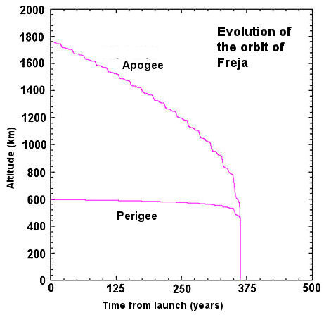
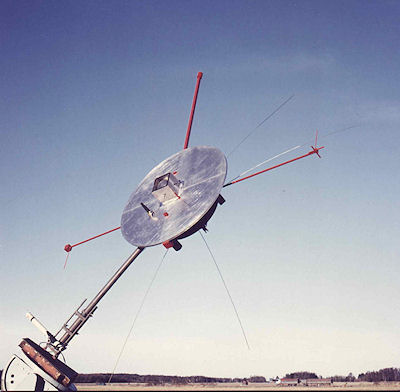
FREJA is a Swedish/German satellite designed for research into the aurora. The satellite was launched "piggyback" on a Long March 2C (CZ-2C) rocket from the Jiuquan Satellite Launch Center (41° N, 100° E) in China on 6 October 1992 and weighed 256 kg at launch. The orbit ranged between 600 and 1720 km altitude at an inclination of 63°. FREJA is a sun pointing spinner (10 rpm) with a 2.2 m diameter.
The Swedish Space Corporation was the Prime Contractor on behalf of the Swedish National Space Agency. Project Scientists were Prof Rickard Lundin at the Swedish Institute of Space Physics in Kiruna and Prof Gerhard Haerendel, Institut für extraterrestrische Physik, Max Planck Institut, Garching.
FREJA made high-resolution measurements in the upper ionosphere and lower magnetosphere in the tradition of Sweden's first satellite, VIKING, launched in 1986. The high resolution was made possible by an S-band downlink with a maximum experiment data rate of 501.4 kbps. The scientific payload composition is shown in the table below. Data was received at Esrange, Kiruna, Sweden and at the Prince Albert Satellite Station in Canada's Saskatchewan province. Prince Albert was well located to receive real time data when the satellite traversed the auroral oval. Commands were only be transmitted from Esrange. FREJA had a stored-command capability in order to operate over Canada without a real-time command link.
| Nr | Experiment Name | Principal Investigator | Mass (kg) | Power (W) | Data rate (kbps) |
| F1 | Electric Fields | Royal Inst. of Technology, Sweden | 5.37 | 9.0 | 30.7 |
| F2 | Magnetic Fields | APL/Johns Hopkins Univ., USA | 3.97 | 4.0 | 14.33 |
| F3C | Cold Plasma | NRC, Canada | 5.79 | 6.2 | 16.38 |
| F3H | Particles; Hot Plasma | Swedish Institute of Space Physics, Kiruna | 9.52 | 15.6 | 42.98 |
| F4 | Waves | Swedish Institute of Space Physics, Uppsala | 8.40 | 11.6 | 42.98 |
| F5 | Auroral Imager | Univ. of Calgary, Canada | 9.94 | 6.7 | 44.01 |
| F6 | Electron Beam | Max-Planck Inst., Garching, Germany |
- |
- | - |
| F7 | Particle Correlator | Max-Planck Inst., Garching, Germany | 8.49 | 13.0 | 26.61 |
| 6 wire booms (l<15m) and 2 stiff (l= 2m) |
21.60 |
- |
- | ||
| Housekeeping |
- |
- |
5.13 | ||
| Synchronization |
- |
- |
6.15 | ||
| TOTAL |
73.08 |
66.1 |
261.98 | ||
FREJA had a total budget of less than 160 MSEK including satellite, experiments, launch and operations. This low cost was partly due to the use of a piggyback launch opportunity, but also to the streamlined project organization and competitive procurement. The project was initiated when the CZ-2C launch reservation was "left over" from the cancelled Mailstar project, a store-and-forward low-orbit communications satellite. The launch reservation was the result of a competition for launching Mailstar, and not particularly adapted to an auroral mission. However, the inclination provided by the CZ-2C (63°) was high enough to stimulate the interest of Swedish scientists into using it for an auroral research mission. The launch price was very attractive, making it feasible to build a satellite despite the acute lack of funds in the Swedish space budget. The funds available were less than half the cost of the low-cost VIKING project (VIKING satellite [excl experiments] and launch: 238 MSEK in 1991 price level). The Swedish National Space Agency and scientists showed great trust in SSC and let the company use unconventional methods to cut costs.
The table below summarizes the design and development costs of the FREJA satellite (excL experiments) plus the launch cost in current prices. In this calculation the dollar has been assumed to be worth 6.60 Swedish Crowns.The financing of these costs came from
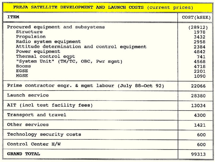
Also, it should be noted that experiment development costs are not included above, but they were covered by the Space Agencies of the respective country of origin of the Principal Investigators (PI). It is difficult to estimate experiment development costs, but an educated guess is that they could amount to maybe 50% of satellite development and launch costs.
In 1992 operations planning and actual spacecraft operations for 18 months was estimated to cost about 12 MSEK. Thus, total project costs including everything was the estimated to be on the order of 160 MSEK.
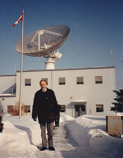
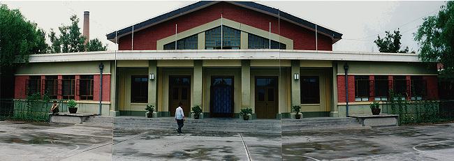
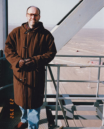
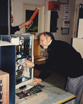
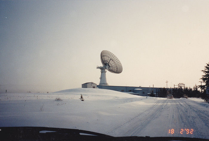
The
Prince Albert Satellite Station, one of Canada's contri-
butions to the
project. In the picture:SSC's Bengt Holmqvist
at a visit in February 1992.
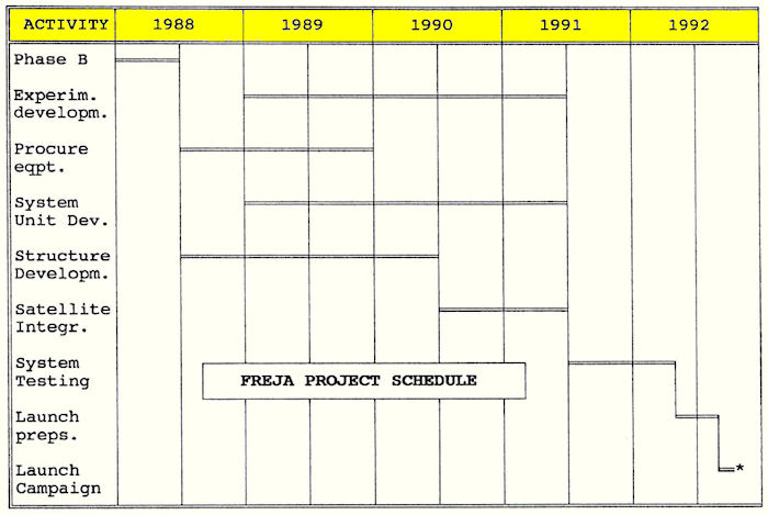
The schedule of the project has been determined by the time needed to design the experiments. The launch was delayed from 1991 to 1992 to allow enough time for experiment development. One must remember that these instruments were really "at the cutting edge of technology" and in many respects much more sophisticated than satellite subsystems. The bar-chart below summarizes the project schedule.
The Long March 2C (CZ-2C), is a two-stage liquid fuel rocket manufactured by what was the called the Beijing Wan Yuan Industry Corporation under the Ministry of Aerospace Industry. The lift-off mass was about 191 tons and the lift-off thrust is 2747 kN. The rocket was 34 meters long and had a diameter of 3.35 meters. Both stages are propelled by N204 and UDMH - Unsymmetrical DiMethyl Hydrazine, H2NN(CH3)2.
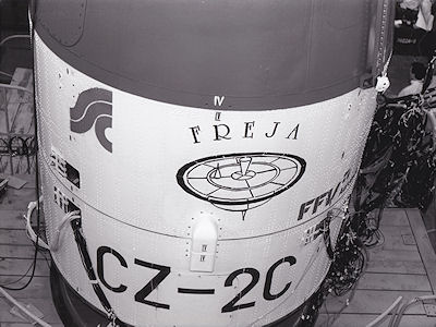
 For launching FREJA the CZ-2C
was modified by the addition of a cylindrical transition bay (or "piggyback
cabin") between the Chinese FSW-1 satellite and the top of the second stage of
the CZ-2C. The transition bay was split into two cylindrical sections. The FREJA
satellite had an interface ring which was clamped between the outer rims of
these two cylinders.
For launching FREJA the CZ-2C
was modified by the addition of a cylindrical transition bay (or "piggyback
cabin") between the Chinese FSW-1 satellite and the top of the second stage of
the CZ-2C. The transition bay was split into two cylindrical sections. The FREJA
satellite had an interface ring which was clamped between the outer rims of
these two cylinders.
Upon reaching orbit the main satellite (FSW-1) was separated by firing four explosive bolts at the interface between the transition bay and the FSW-1. At the same time retrorockets at the rear end of the CZ-2C second stage fired and ensured a smooth separation of the main satellite.
The table
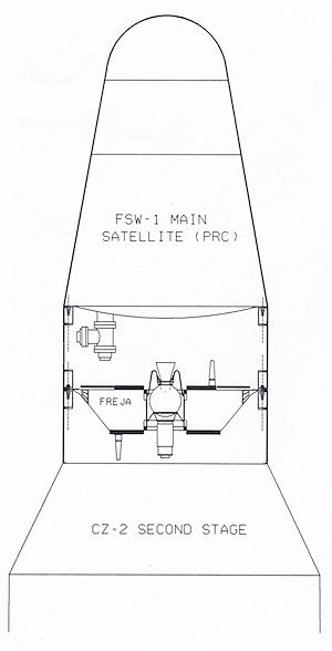
below shows the nominal sequence of flight events up to FREJA separation. 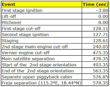 The
picture on the right shows the cylindrical transition bay (or "piggyback
cabin") between the Chinese FSW-1 satellite and the second stage. The mechanical interface between the
CZ-2C and the satellite is provided by an aluminium ring which
is clamped betwen the two halves of "piggyback cabin". The main
satellite is released first while the CZ-2C stage is under 3-axis
control.
The
picture on the right shows the cylindrical transition bay (or "piggyback
cabin") between the Chinese FSW-1 satellite and the second stage. The mechanical interface between the
CZ-2C and the satellite is provided by an aluminium ring which
is clamped betwen the two halves of "piggyback cabin". The main
satellite is released first while the CZ-2C stage is under 3-axis
control.
After a reorientation maneuver to put the separation vector parallell to the orbital tangent at the orbital apexes, the top half of the "piggyback cabin" was separated by firing four explosive bolts. These bolts only acted on this part and FREJA gently moves away from the CZ-2C stage which is braked by small solid rockets. At separation the angular rates of the second stage were very low ( <0.35°/sec).
A few seconds after separation solid propellant spin rockets are fired to give FREJA a 50 rpm spin in preparation for ignition of orbit adjust motors. The CZ-2C puts FREJA into a 203-317 km parking orbit at 63° inclination. This orbit must be raised to reach scientifically interesting regions and to keep the satellite from decaying.
The Thiokol STAR 13 A rocket motor fired at the southern apex of the parking orbit to give FREJA an apogee of about 1700 km. As this apogee was reached approximately 50 minutes later the STAR 6B motor fired to raise perigee to 600 km, high enough to avoid rapid decay of the satellite.
The launch site for the FREJA satellite was the Jiuquan Satellite Launch Center in the Gansu province of the People's Republic of China at approximately 41.3°N 100.3°E. It is operated by what was then called the CLTC, "China Satellite Launch and Tracking Control General", an organization under soemthing then called the Committee of Science, Techno logy and Industry for National Defense (COSTIND). The center is linked by rail and road to the nearest airport (Airport #14) 94 km south of the launch site. The video below shows how Freja arrived at the aiport of the launch site.
The launch site at that time consisted of a Base Area with a residential area, shopping center, bank, post office, movie theatre, TV station, hotel facilities, schools, power station and the range control center. This base area is called Dong Feng, "The East Wind".
The Technical Center for the CZ-2C rocket and its payload is roughly 20 km north of Dong Feng and this is the place where the launch vehicle is assembled and checked out horizontally. FREJA was checked out in a separate building (BM) near the launch vehicle integration building. FREJA pyrotechnics and rocket motors were stored in a room in the BM building.
|
|
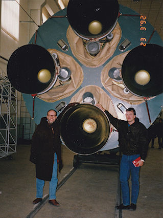 A crew training version of a CZ-2C launch vehicle at the Technical Center. Sven Grahn, SSC, on the left, Stig Alterbäck, FFV, on the right. |
The Launch Pad used in 1992 for CZ-2C launches is situated another 30 km north of the Technical Center. The launch vehicle and satellites are transferred by road to the launch pad.
The hotel where the Freja
team stayed.
For a lift-off mass of about 259 kg the pre-launch timeline below was calculated. The timer function of the FREJA System Unit fired rocket motors, deployed antennas and started transmitters at the times indicated below. After the fourth Esrange contact the transmitter in the satellite was operated by ground commands, direct or stored, instead of the pre-programmed events in the on-board computer memory.
|
Event |
Hr:min.sec |
| Lift-off |
0.00 |
| Injection into 203-317 km orbit (Position:18.44 N,115.28°E) |
9.38 |
| Spin up of FREJA to 50 rpm by solid spin rockets. |
9.48 |
|
Maneuver 1 at rev 1 apogee puts FREJA in 285-1723 km transfer orbit. Sat. position:63°S, 156°W.Delta-V=386.4 m/s |
36.36 |
|
Maneuver 2 at transfer orbit apogee puts FREJA in final 599-1725 km orbit with a 108.6 minute period. Sat. position: 62°N, 9°E Delta-V=84.1 m/s |
01:29.24 |
| Spin down of FREJA to 11 rpm by solid spin rockets. |
01:31.24 |
|
Start Low-Speed Link transmitter. Receive at JSLC. |
01:32.09 |
| Stop Low-Speed Link transmitter |
01:55.00 |
| Deploy S-band antennas |
02:26.00 |
| First Esrange Contact start |
03:11.24 |
| First Esrange Contact end |
03:34.24 |
| Second Esrange Contact start. |
05:03.54 |
| Second Esrange Contact end |
05:23.48 |
| Third Esrange Contact start |
06:56.30 |
| Third Esrange Contact end. Last Esrange pass Day 1. |
07:10.54 |
| Fourth Esrange Contact start |
17:36.36 |
| Fourth Esrange Contact end. |
17:43.18 |
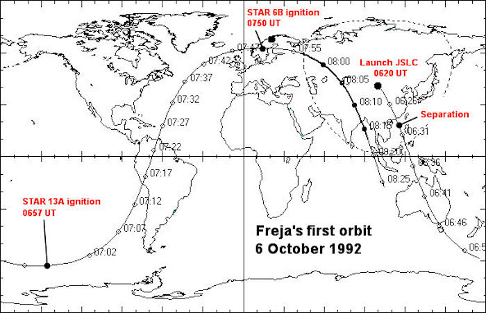
The map below show where the satellite was from launch up to and including the moment when the Low Speed Link was first turned off. The radio horizon around JSLC is shown.
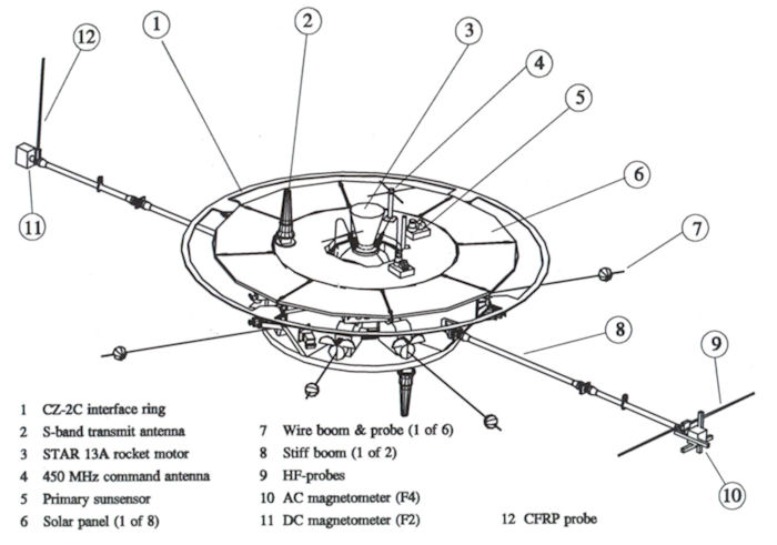
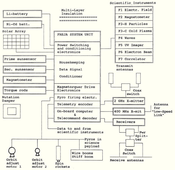
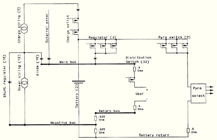
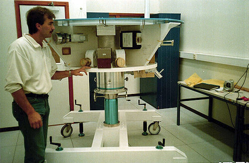
A block diagram of the satellite is shown below.
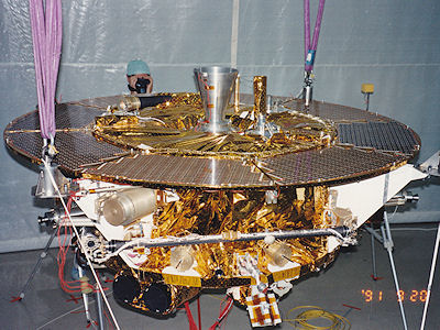
The structure consists of a central tube machined from cast magnesium. Inside this the solid rocket motors are mounted on a Kevlar adapter to limit heat soak into the satellite from the spent motors. The pictures and sketch below illustrate the stucture concept. In the photograph the launch vehicle interface ring is not mounted.
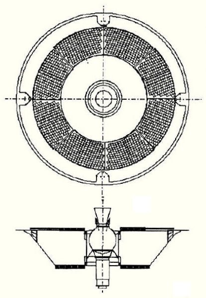
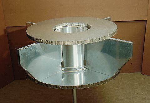
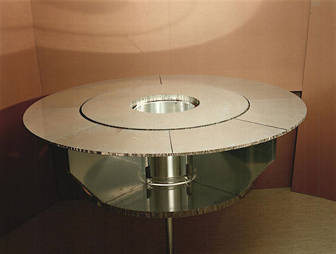
Four radial walls connect the central tube with the CZ-2C interface ring and on the top and bottom of the walls the top and bottom platform decks are mounted. Platform and science equipment are mounted on the walls and the platforms.
The unusual mechanical interface to the launch vehicle and the need to locate wire boom assemblies and scientific instruments on the largest possible radial distance from the spin axis made it impossible to locate solar panels on the outside perimeter of the satellite.
The top surface was used to locate the solar panels and a sun-pointing attitude gives maximum electrical power (130 W End-Of-Life) and acceptable, albeit not optimum, viewing angles for the scientific sensors. This mounting of the solar panels leaves the back of the panels free so that heat can be radiated.
Spin-stabilization was needed to keep the so called wire booms for measuring electric fields extended. Also, it is suitable for a satellite making a two-impulse Hohmann transfer. The two rocket motors can be placed along the spin axis with nozzles pointing in opposite directions. The spin vector attitude was controlled by the well-proven quarter-orbit magnetic torquing method. This was used for FREJA to make the spin axis track the sun. A three-axes magnetometer, redundant solar aspect sensors and an IR earth sensor were used for attitude determination.
Redundancy was used whenever possible. FREJA has redundant transmitters, receivers, batteries, solar array shunts, telemetry systems, telecommand decoders, computers, pyro circuits and attitude sensors and actuators.
The Central Tube made by the Weda foundry, Sweden connects the vertical aluminium honeycomb walls. It also provided a mounting interface for the mounting of the STAR 13A and STAR 6B motors as well as handling points for the Mechanical Ground Support Equipment (MGSE). The central tube is made of cast magnesium and has an overall thickness of 5 mm. The length and outer diameter are 440 mm and 412 mm respectively.
Aluminum Honeycomb Panels made by Hexcel, Belgium are used as the structural members of the satellite on which other equipment units are mounted. They consist of Al/Al honeycomb core sandwiched between thin aluminium sheets glued to the core. The core is manufactured by Hexcel and is corrosion resistant and perforated. Commercial aircraft grade honeycomb has been used to reduce price. Dimensional tolerance for this grade was stated to be 0.2 mm/100 mm but was found to be about 2-4 times better. A thicker adhesive is required than for "space- grade" honeycomb panels, which adds about 300 grammes/m2 compared to a standard space adhesive (Redux 312L).The total mass penalty for FREJA was not more than 800 grammes, while material costs were reduced by a factor of 10. With the exception of the radial walls (see section "Satellite Configuration") which required integrated edge-beams, all panels were cut out of large standard platforms.
Structural inserts interconnecting honeycomb panels were bonded when the panels were in place, assuring a stress-free structure in spite of dimensional mismatches on the order of 0.5 mm due to panel non-planeness.Potted equipment inserts were not mounted flush with the panel, but were manufactured with a flange of initially 1mm thickness. Each set of inserts corresponding to one box attachment were then milled flat in one operation. The milling operation, while non-trivial, could be performed in a well-equipped machine-shop and was not particularly costly.The insert flange was bonded on the lower side to the panel facesheet, resulting in a torque capability exceeding that of the screw, although the weight of the insert was comparable to a standard Shur-Lock insert.
A new procedure for potting inserts with Stycast 1090 was developed, ensuring a minimum void (approximately 1% as opposed to typically 30% in the Tele-X project). The main feature of the potting procedure was potting the inserts upside down and using multiple filling operations, allowing the potting compound to settle in between each operation.
The Rocket Motor Support is manufactured by ACR AB, Sweden. The STAR 13A and STAR 6B rocket motors were mounted inside the central tube. In order to insulate them thermally from the rest of the satellite the structural detail connecting the motors to the central tube had to be manufactured from a plastic material. Therefore the rocket motor support material is Kevlar 49 fibre as a reinforcement to the Eccobond 104 epoxy.
Multi-Layer Insulation material for thermal control is manufactured by the Sheldahl Company, U.S.A The temperature of the satellite was controlled by applying appropriate covers of paint or. insulating blankets. The insulating blankets consist of multiple layers of metallized plastic foil with a plastic net spacer between each layer. The type of foil and its coating varied depending on where on the satellite the blanket shall be mounted. Therefore three different types of foils had to be used on FREJA.
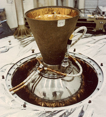 Propulsion system
Rocket Motor no.1, is a STAR 13 A manufactured by Thiokol. This rocket motor is used to raise the orbit of the FREJA satellite. The reason for this is that the Chinese launch vehicle delivered the satellite in an orbit which was too low for making any scientific investigations. The STAR 13 A fired under pre- programmed control from the FREJA System Unit and raised the apogee (high point) of the orbit from approximately 300 to 1700 km. (See picture on the right).
Rocket Motor no.2 , is a STAR 6 B manufactured by Thiokol. The STAR 6B fired under control from the FREJA System Unit and raised the perigee (low point) of the orbit from approximately 200 to 600 km.
Spin Rockets were manufactured by the Beijing Institute of Space Machine and Electricity under the Chinese Academy of Space Technology. Two of these small (Propellant mass: 370 grammes, Total impulse: 750 Ns) solid-propellant rocket motors were used to spin up the satellite after separation from the Long March 2C rockeL Two other of these motors were used to reduce the spin rate after firing of the two Rocket Motors. The ignition of the spin rockets was controlled by an onboard timer function in the FREJA System Unit.
The basic design concept for the power system was developed by Dr Friedhelm Melzner of the Max-Planck Institut in Garching based on experience from a similar system on the AMPTE/IRM satellite. This simple design uses Zener shunt voltage regulator at each of the eight solar panels (130 W EOL). Thus, in sunlight the bus voltage is determined by the solar panels. Separate strings of solar cells on the panels provide enough voltage to charge the Ni-Cd batteries in sunlight. The voltage of the solar panel shunts is slightly higher than that of the voltage regulators connecting the batteries to the main bus via diodes. Therefore, in sunlight the batteries are disconnected from the bus.
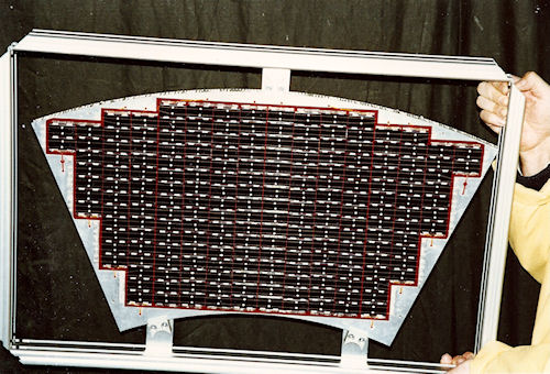
The Solar Array was manufactured by Telefunken SystemTechnik, Germany and provides electrical power to the satellite for operating all onboard subsystems and for charging the Ni-Cd battery. The cell type used is BSFR (Back Surface Field and Reflector) with a size of 19 x 39 mm and a thickness of 250 µm. This cell type has an efficiency of 14% at 25°C, one solar constant and Air Mass Zero. Each cell is covered by a conductively coated cover glass. This is required for scientific reasons since the satellite's electric potential has to be as close to that of the surrounding space plasma as possible. The cover glass material is Cerium-doped microsheets (CMX) with a 300 µm thickness and coated with ITO (Indium-Tin-Oxide). The whole solar array consists of 8 panels each having 200 cells. Thus, entire array has 1600 cells and generates 168 Watts maximum. The cells are mounted on an aluminium honeycomb substrate with a 15.6 mm thickness covered with a 50 micron thick KAPTON H foil. One of the eight panels is shown below.
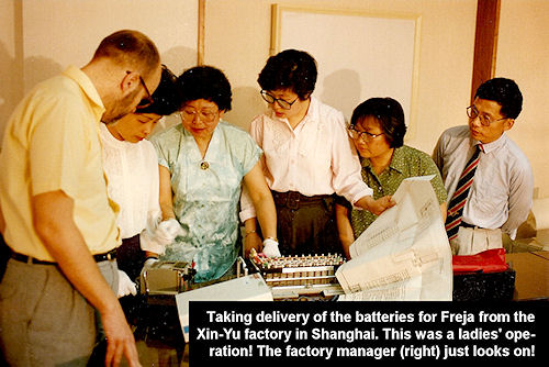
The Nickel-Cadmium Batteries were designed and manufactured by the Shanghai Institute of Space Power Sources, China. Two such batteries are installed in the satellite, one being an "in-orbit spare". Each battery contains 24 cells, has a rated capacity of 6 Ah and weighs 8 kg.
The Lithium Battery was manufactured by ElektronikCentralen, Denmark and provided power to the satellite during the initial phase of the mission immediately following separation from the launch vehicle. During this period the solar array was not fully illuminated by the sun and the satellite needs to be turned. Power to this turn with the magnetic torquers is drawn from the Ni-Cd batteries, but these needed to be augmented during the first two days in orbit by an expendable primary battery - i.e. the Li-battery.
Simulations of the orbit determination problem for FREJA showed that it was sufficient to use angular tracking with the 9 meter S-band receive antennas that SSC has at ESRANGE at that time. Thus, no ranging is needed and therefore no transponder. Separate transmitters and receivers could be used. Such units are much less costly than a full transponder. Redundant 2 Watt S-band PM transmitters were used.
Very simple, reliable and rugged FM receivers were used. These redundant units are similar in design to the range safety receivers used on launch vehicles. They operated in the 450 MHz Earth-to-Space band allocated by the ITU. At this frequency the Doppler shift is low, and the signal spectrum is quite narrow. Therefore a simple FM receiver without PLL tracking of the uplink could be used. The signal on the uplink was a simple bi-phase-L PCM signals at 1200 bps.
S-band transmit antennas were manufactured by what was then Ericsson Radar Electronics, Sweden (nowadays RUAG Space). One of these antennas was mounted on each side of the satellite (sunlit and dark side) . These conical helix antennas were used to transmit the data from the satellite "platform" and the scientific instruments to the ground stations.
450 MHz command reception antennas were manufactured by FFV Aerotech, Sweden. One of these turnstile antennas was mounted on each side of the satellite (sunlit and dark side).
S-band transmitters (T-102SE) were manufactured by what was then Aydin Vector, U.S.A (nowadays L3). The satellite carries two of these units. One of these was an "in-orbit spare". They both operated at 2208.1629 MHz with 2 Watts nominal output power.
Command receivers (RCC 500) were manufactured by Aydin Vector, U.S.A. The satellite carried two units to receive commands from the ground. One receiver was an "in-orbit spare". They both operated on 449.95 MHz.
The high speed data link from FREJA operated on 2208.1629 MHz at 2 Watts RF output power. The 262 kbps data stream was phase-modulated on to the carrier . A doubling of the data rate to 524 kbps was also provided.
A low speed data link on 400.55 MHz (2 Watts RF power) which sent AFSK signals at 1200 bauds was intended to send housekeeping signals to receivers on the ground equipped with omnidirectional antennas. By using a simple AFSK decoder and a personal computer the state of onboard equipment could be checked. The onboard antenna for this link was a whip antenna for cellular phones used on cars. This linked worked, but the fading of the signal due to the rotation of the satellite limited the usefulness of the system.
Spin-stabilization was used to keep the so-called wire booms for measuring electric fields extended. Also, it is suitable for a satellite making a two- impulse Hohmann transfer. The two rocket motors can be placed along the spin axis with nozzles pointing in opposite directions. Since the CZ-2C did not provide any spin the satellite had to spin up from zero spin rate as soon as possible after separation. This was done within 10 seconds after separation so the depointing caused by residual rates did not affect the final orbital parameters very much.
The well-proven quarter-orbit magnetic torquing attitude control method was used to make the spin axis track the sun. However, a low orbit gives a good magnetic control authority, but it also causes strong gravity gradient disturbance torques for a satellite with long wire booms. These torques caused spin axis movements of the same order of magnitude as the motion of the sun in inertial coordinates.
The Primary Sun Sensor was designed and manufactured by Science Management and Engineering GmbH, Germany (see picture below). This unit measured the orientation of the satellite's spin axis relative to the direction of the sun during the collection of scientific data. The key sensing element is a Linear CCD Image Sensor (TH 7805A(Z)) manufactured by Thomson CSF, France.

The Secondary Sunsensor was designed and manufactured by ACR AB, Sweden. This unit measured the orientation of the satellite's spin axis relative to the direction of the sun during the initial phase of the mission (2 days) when the sun was not aligned with the spin axis, but instead >90 degrees from the spin axis. The key sensing element was a Position Sensitive Photo Detector Type 2L4 from SiTek.
Magnetic Torque Rods (D42653,032660) were manufactured by ITHACO Inc., U.S.A These units are electromagnets used to change the orientation of the spin axis and the spin rate of the satellite.
When current is applied to the Precession Torquer it interacts with the Earth's magnetic field and generates a torque which turns the satellite. When current is applied to the Spin Torquer it interacts with the Earth's magnetic field and generates a torque which changes the spin of the satellite. The current has to be applied with different polarity as the satellite spins. In fact the Spin Torquer can be seen as the rotor in a DC electric motor where the Earth's magnetic field is the stator field. Commutation of the current was provided by the magnetometer.
The Magnetometer (SAM-72C-HR) was manufactured by the Schonstedt Instrument Co., U.S.A and measured the three components of the Earth's magnetic field and this data was transmitted to the ground where they were used to determine the orientation of the satellite. Also, the magnetic field component perpendicular to the spin axis was used by the FREJA System Unit to determine when to change the polarity of the current in the spin rate-control.
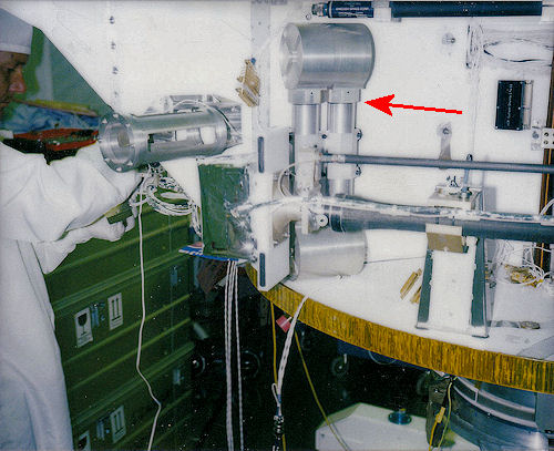
The Nutation Damper was designed and manufactured by the Max-Planck-Institut in Garching, Germany. This unit consisted of a closed aluminium tube filled with a viscous fluid (Fluorinert FC-43 made by 3M). The viscous damping characteristics of the fluid reduced any irregularities in the spinning motion of the satellite. One of two nutation dampers is shown at the red arrow below.
Normally units that provide "platform functions" are procured from different sources and their interconnection is covered by elaborate internal interface specifications. For FREJA a scheme was adopted that was used on AMPTE/IRM and other satellites, i.e. to have a common unit performing most "platform functions". Outside this unit are only batteries, solar panels, attitude sensors, attitude actuators and propulsion units. In FREJA this unit was called the FREJA System Unit (FSU). The picture below shows the FSU with radio units mounted on its side.
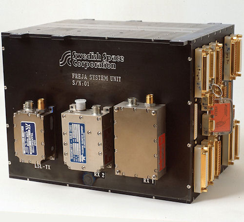
It is a 13 litre box weighing approximately 15 kg containing 13 printed circuit boards (220x260 mm). It performs the following functions:
The FSU, developed by the Swedish Space Corporation, was fully redundant and used MIL 883 B-level components. The onboard processor was Matra-Harris' 80C31.
Combining these all these functions in one unit saved interface engineering costs. One person handled the interface work as an integral part of the design process. Of course this advantage was partly offset by more complex testing of these functions.
The FSU communicated with experiments through a single connector only carrying a two way serial link via opto-couplers and 28 VDC for powering the experiment and a heater power circuit. All telemetry data going to the ground were also available to all experiments and commands are sent to the experiments only as part of this serial bitstream. No high level commands (relay closures) except pyro firings were provided by the FSU.
This very clean interface to each experiment was be simulated by an extension board to a personal computer - a "satellite emulator" against which each experiment could be designed and tested. When the experiments arrived for integration on the satellite the data handling interface rarely presented problems.
The Wire Booms (Type 84100) were made by Weitzmann Consulting Inc, U.S.A and supported the F1 (Electric Fields) and F4 (Waves) experiments. Wire boom systems contain a reel of cable connected to a spherical electric field sensor. The wire boom systems reeled out the cables to 15 meters length when the satellite had reached its final orbit the spin of the satellite kept the wire taut. The wire was actually a multiconductor cable which transferred signals from the spherical tip sensor to the electronics units of the F1 and F4 experiments. Thus, each of the six Wire Boom systems consisted basically of a cable reel, a DC electric motor, the cable, various switches and connectors and structural details.
The Stiff Booms were designed and manufactured by Science Management and Engineering GmbH, Germany. There are two stiff booms on FREJA, each 1.9 metres long. Their purpose was to extend the flux gate (F2 instrument) and search coil (F4 instrument) magnetometers from the satellite body. Two other sensor probes were also attached to the booms, namely the so-called Langmuir and high-frequency probes (F4 instrument). The two booms each have two hinged sections. Each boom section consists of a combination of glass fibre and CFRP (Carbon-Fibre Reinforced Plastic).
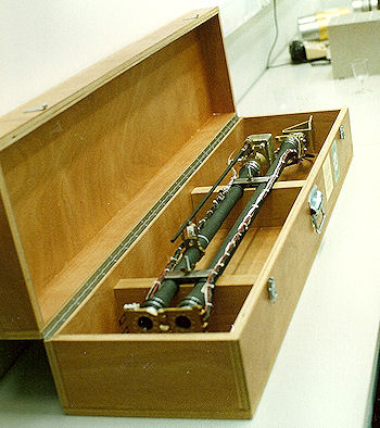 One stiff boom system delivered to FFV Aerotech in Arboga. |
|
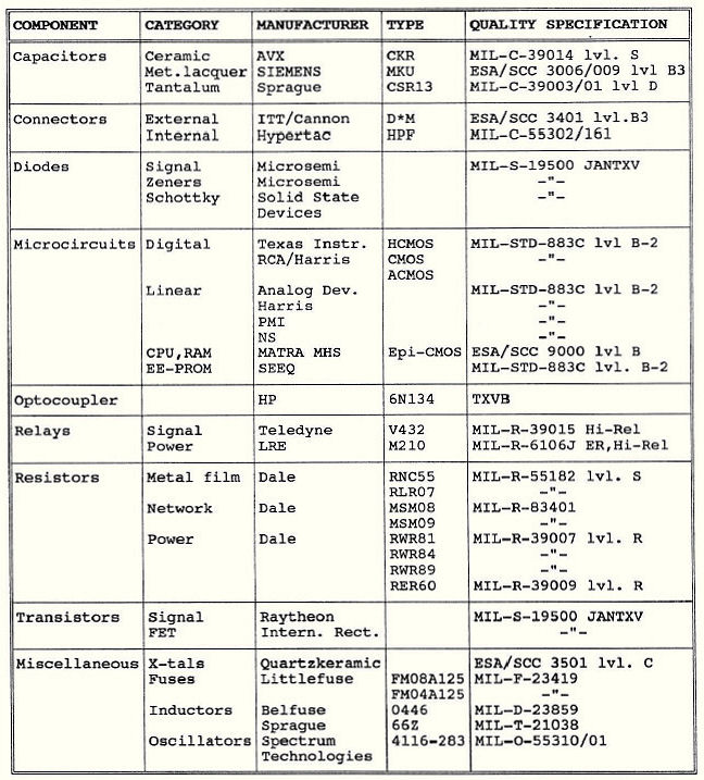
A decision was made early in the project not to buy "space-qualified" components for the "System Unit" because of their intolerably long delivery times. A different component specification also saved costs. Thus, MIL-STD parts were bought having a radiation tolerance several times higher than the 2.6 kRad total radiation dose expected during the mission and also reasonably insensitive to Single Events. Critical components (CPU, RAM,..) were bought to higher specifications. Receiving inspection and test (parameter testing) was used on all electronic components. Below follows a list of EEE-parts in terms of manufacturer, types and specification.
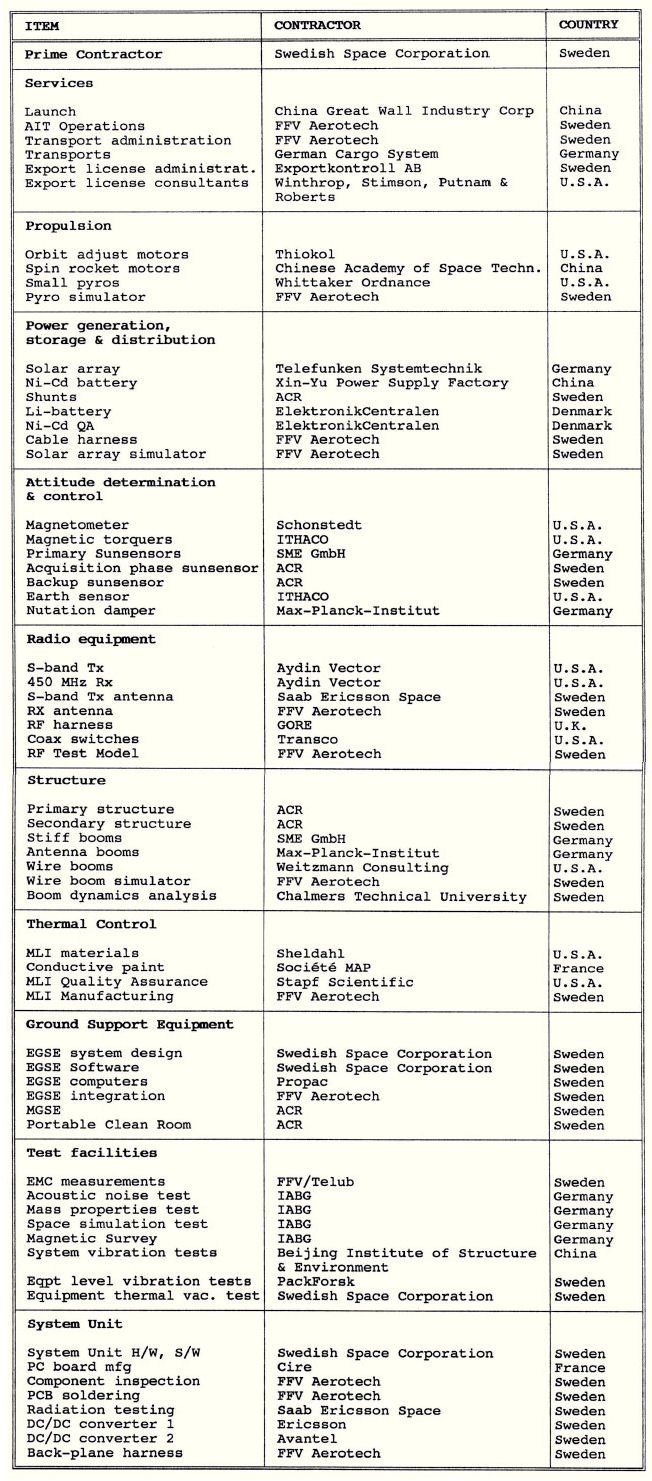
Competition
Wherever possible,
competition was used in procuring equipment and services. During phase B
competing proposals were submitted for all hardware and manpower tasks. In the
development phase suppliers were chosen from these bidders, except when a
country participating in the project contributed in kind with hardware or
services. A list of suppliers is found in the table following this
section.
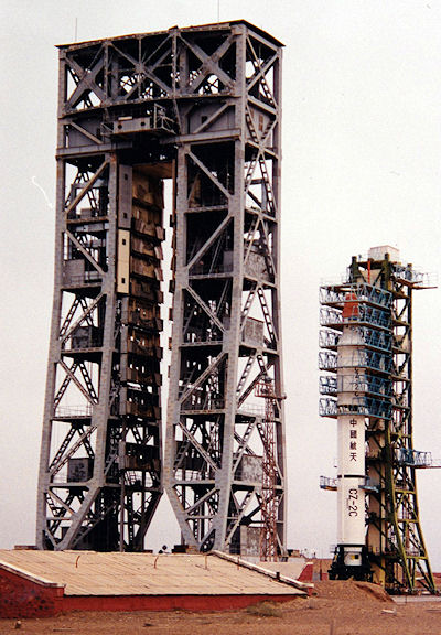
The CZ-2C and Freja ready for launch. No connection
with text on the left :-)
Elimination of subsystem
contractors
Swedish Space Corporation as the Prime Contractor for
FREJA assumed subsystem responsibility and only procured on equipment
level. Since many units were off-the-shelf equipment and because the "System
Unit" combined several subsystems such an approach is possible for a very small
project team (9 persons). It will save money by avoiding the costly layers of
management that subsystem contractors would introduce. Not only is a layer of
management avoided but also a layer of documentation.
Limited subcontractor
responsibility
A subcontractor, FFV Aerotech, carried out the
practical work of assembling the satellite, transporting it to the test sites
and carrying out the tests as specified by SSC. The "Assembly, Integration &
Test" (AIT) contractor had a work force consisting of 6 persons. The AIT
contractor was given practical tasks and was not required to take any
significant technical risks. This made it possible to keep the AIT contract sum
low and also to obtain a fixed price contrac. SSC absorbed the technical
risk.
Another potential advantage of limiting supplier technical responsibility and financial risk is that smaller companies can be used. Such smaller suppliers may be very skillful, unbureaucratic, have small overhead costs and offer quick tum-around times, while not being able to absorb so much risk.
Fixed price
contracts
All equipment contracts and most service contracts were
fixed price contracts. U.S. companies offered firm, fixed contracts, while
European suppliers insisted on escalation clauses!
Minimize documentation
requirements
Suppliers of off-the-she lf equipment were encouraged
to propose minimum documentation while adhering strictly to their normal
quality and test procedures. Preparing documents is very costly, and by asking
the supplier to use the methods of QA and test employed in delivering
equipment to ESA, NASA or DoD, the project essentially "piggybacked" on the QA
requirements of these organizations.
Costly equipment acceptance tests performed
"in-house"
In addition, SSC made additional savings by performing
certain equipment acceptance tests in-house. It was, for example, found very
expensive to let the vendors perform thermal vacuum testing of the hardware. The
price was typically USD 10,000 per unit. These tests were performed in-house by
SSC on many units: Rx, Tx, Sun sensors, shunts etc..
Although this could have put SSC in a difficult contractual position had the equipment failed during this test, it turned out that the vendors will make repairs free-of-charge, even if this is not explicitly stated in the contract. For some units, thermal vacuum tests were deleted based on the recommendations and experience of the vendor (e.g. torque rods).
Performance incentives
Such incentives were used once in the project. The
contractor used to make production drawings for the structure, manage all
workshops and assemble the structure was given an incentive of 15000 SEK/kg of
reduced mass. At that point the satellite was overweight by 5 kg. The contractor
shaved off 15 kg(!) from the specified structure mass. Of course SSC had to make
all the analyses to prove that the structure was strong enough to withstand
tests and flight.
Limit flight spares
For several units (especially non-electronic), flight
spares were not ordered. It was ensured however that a sufficient number of
critical parts was available at the vendor to enable rapid repair if necessary:
E.g. wire booms, stiff booms, mechanisms, S-band antennas. This arrangement has
saved money.
To keep costs low engineering work has been streamlined whenever possible. Some examples of such methods are given below.
Avoid "analysis
over-kill"
For example, all equipment brackets were not analyzed, only
those which were found to be subjected to significant forces. The remaining
brackets were qualified during the qualification vibration test. The gains in this case were off-set by
the fact that it was found after the vibration tests together with the main
satellite that the vibration levels specified by the launcher agency were too
low, thus requiring additional analysis at a fairly late stage.
Sometimes it is less costly to make a design change than to continue a costly analysis of an existing design. This was the case when a problem was identified which required knowledge of the temperature of a solid rocket motor casing after firing. A preliminary analysis costing several tens of thousands of SEK performed by the motor manufacturer gave a predicted temperature in the range of 230-480°C. The critical temperature which the motor structure temperature could not exceed was approximately 290°C. A detailed, but expensive, analysis was offered. Rather than performing this, the problem was "removed" by attaching a temperature resistant spacer between the motor and the motor mount. The design change was much less costly than the continued analysis which would probably have led to the design change anyhow!
Contract "one-shot analyses"
to external experts
Structural and thermal analyses are tasks that
extend for a large fraction of the project duration and are tightly bound to the
system design. Therefore the project team shall be able to do these within
itself. However, specialized, "one-shot" analysis tasks should be given to
external experts. For
example, a modal analysis of the wire boom dynamics was performed by Mr. E.
Crellin of ESTEC, and a transient dynamic analysis (for the wire boom deployment
operations) was' performed- by an outside contractor (Chalmers technical
University, Sweden).
Remove tests and rely on
analysis
The nutation damper design (tube and endpots) was based on
theory found in a Fokker study which was part of an ESTEC contract. The
calculated performance was checked with tested performance of similar
dampers.used on-the Ge rman AMPTE satellite, and found to be acceptable.
Actual testing of the
FREJA dampers was therefore deleted, resulting in cost savings of
approximately USD 30,000.
Qualify during system vibration tests
It was the experience during the Tele-X communications
satellite project that many large appendages such as antenna reflectors and
solar panels were overtested during equipment vibration tests due to
non-representative mechanical interfaces. The equipment level vibration test requirement
for the Freja solar panels was deleted and the qualification of the panels was
instead performed during the system acceptance vibration test. The intention initially was to have at
least one flight panel ready for the system qualification vibration test, but
the panel was not ready in time.
Avoid
multiple specification margins
Typical equipment vibration qualification levels for FREJA
equipment were set at 15 g's between 10-100 Hz. For FREJA, significant
notches (down to 2 g's) were granted to certain experiment units in their
equipment vibration specifications. These notches were based on the preliminary
coupled analysis results and the results of the structural qualification
vibration tests.
As FREJA subsystems were not contracted out, no extra margins were imposed as is often the case. With such extra margins at each contractual level the result is higher and higher equipment vibration specs that eventually could leading to overtest and costly failures of the specimen.
EGSE/Control Center
Commonality
In the VIKING and Tele-X projects considerable costs
were caused by the fact that the EGSE (Electrical Ground Support Equipment)
computers and software were developed by a completely different organization
than the one that developed hardware and software for the Satelite Control
Center. The EGSE and the Control Center have some basic functions in common, i
e. displaying telemetry and issuing commands. In addition there is an immense
problem of configuration management of telemetry calibration functions between
the EGSE and the Control Center.
For FREJA the software for the EGSE and the Control Center at ESRANGE are identical and are produced by one and the same person. Both the EGSE and the Control Center used "IBM-compatible" PC:s equipped with 80386 microprocessors (+math co-processor) operating at 33 MHz. The only difference between the hardware is that the Control Center has a LAN with a file server, while the EGSE has two stand-alone PC:s (one for TM display and one for telecommanding).
Use powerful and easily
available analysis tools
The following powerful analysis tools have
been invaluable for the project:
These tools are directly available to the project team and analyses are run within hours of finding problems. No work-orders or con tract negotiations were required. The work was just made when needed!
Use ESA expertise
Being a member state in ESA, the availability of help and
advice from the staff of ESTEC is invaluable. Help from ESTEC in the
following areas were greatly appreciated:
Equipment level
models
On equipment level, "off-the-shelf" equipment required only
acceptance testing (or delta-qual if FREJA qual levels exceeded
previous qual levels), while new equipment required an engineering model,
a qualification model/flight spare and a flight
unit.
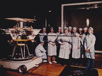
The protoflight satellite
For FREJA one complete satellite model was built, the
"protoflight" model, which was subjected to qualification tests
and used for actual flight. Qualification of the
structure as well as system level acceptance vibration tests were performed
in China, while space simulation tests were performed at IABG, München.
The flight structure with equipment mass dummies mounted was used for thermal
blanket manufacturing and fitting.
The "bench test model"
However, a "bench test model" (BTM) of the satellite was
built up in SSC's lab in Solna early in the program. This consists of the
breadboard model of the System Unit, a copy of the flight harness, commercial
grade batteries, simulators for solar panels and wire booms, engineering model
or breadboard experiments, engineering models of new equipment (attitude
sensors), flight spares for receivers and tramsmitters, flight units for
antennas, pyro simulators.
The BTM was used to verify System Unit hardware and software design. It is also used for "hunting" EMI, testing onboard and ground software. The breadboard System Unit hardware and software configuration was updated to be similar to the flight unit.
The BTM was in use daily throughout satellite integration and environmental tests for troubleshooting. The BTM is a cost-saving tool. Time consuming trouble-shooting tests need not be performed on the flight satellite, but can be performed unhurriedly in parallel with satellite testing. The video clip below gives an impression of the BTM.
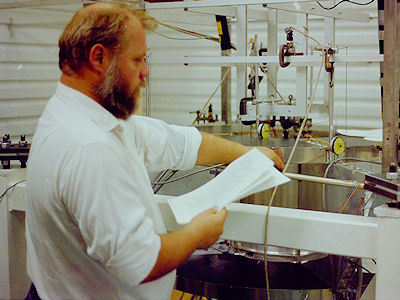
The wooden mockup
Harness routing was performed on a high fidelity
wooden mock-up using the same equipment mass dummies that were later used
for the system qualification vibration test. The picture below
was taken at FFV Aerotech in Arboga. AIT manager Stig Alterbäck poses next to
the wooden mock-up.
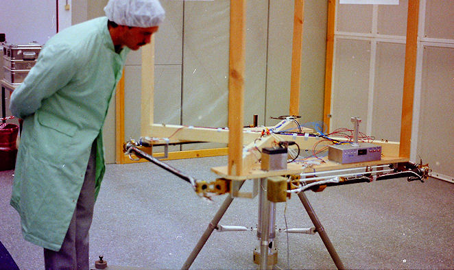
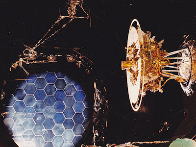
The radio-frequency test
model
A full scale sheet-metal model of the satellite with a
prototype TC antenna and the Ulysses flight spare TM antenna (on loan from
ESA) was used early in the project for antenna range measurements aimed at
finding the optimum location of TM and TC antennas. This model was updated and
used with FREJA flight antennas to make a final verification of antenna
radiation patterns. The Rf test model under test at FFV in Arboga is shown
below.
System Level Tests
Except for the use of the protoflight model philosophy on
system level no normal spacecraft system tests have been deleted from the FREJA
development program. In addition to the antenna range measurements made on the
RF test model, the following tests have been performed on the
protoflight satellite:
|
|
|
|
|
|
|
|
|
Customer Relations
A
cost-saving feature in the FREJA project has been the very flexilble attitude of
the Customer (the Swedish National Space Agency, SNSA) regarding reporting.
Because of the co-location of SSC and its Customer, oral reports are given
directly to the President of the Board on a day to-day basis. Formal, brief
written reports were been submitted at roughly two month intervals in connection
with meetings of the Science Committee and board of
directors of the SNSA. The SSC project manager also issued a
"Project Newsletter" at three-month intervals giving news about progress and
problems.
The technical interface with the Customer was the Project Scientists. SSC discussed directly with Professors Lundin and Haerendel about satellite performance and technical risks. Such matters were also freely addressed at the Science Team meetings held every six months. At such meetings scientists and engineers from PI:s and Col:s participated without limitation. Design reviews were been attended by SNSA administrators and scientists and engineers from the experimenters.
Of course, SSC's project team realized that this attitude of the Customer was a result of their trust in us, something we appreciated very much and constantly worried about being worthy of.
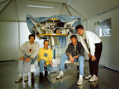
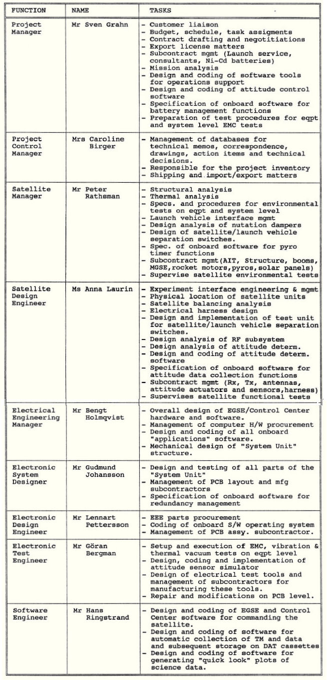
The small project team - the
"sink- or-swim" approach
When starting FREJA it was evident that the
only chance to meet budget constraints was to use a very small, multi-skilled
project team throughout the design, development and test phase. A table below
shows how SSC's project team members covered many aspects of
developing the satellite.
Sven Grahn
Caroline
Birger
Peter
Rathsman
Anna Laurin
Bengt
Holmqvist
Gudmund
Johansson
Lennart
Pettersson
Göran
Bergman
Hans
Ringstrand
One of several inspiration sources in organizing the FREJA team has been the "Skunk Works" organization at Lockheed set up by "Kelly" Johnson to develop such airplanes as the U-2 and SR-71 "Blackbird". In his memoirs [1] Johnson listed fourteen points to observe when running a "Skunk Works" organization. The following points are of particular inter est:
In organizing the FREJA project team we tried to follow these recommendations. The same small group has worked on the project more or less full-time. Very little part-time manpower has been used. In this way the risk of a part time worker using more time than allocated in the budget is avoided. However, this philosophy requires that the project team can handle all technical, management and clerical matters (team members typed their own memos and typed and sent letters and faxes - this was in the pre-Internet era). In FREJA, this is what the team was forced to to do; It was a philosophy of "sink or swim"!
Since almost every team member in addition to technical tasks had a subcontractor management task he/she identified with the project, became an active participant in the daily management of the project and was acutely aware of the schedule constraints imposed on the work. So, each team member was important and not immediately replaceable. This presented a risk to the project in case a team member left the company, became ill or is otherwise incapacitated - soemthing that did not happen.
However, these risk are greatly outweighed by the many,advantages in having.a small project team. Below follows a description of some of the more obvious.
Minimizes costly
interface work
A small team minimizes interface work. For example, a
two-person team at SSC were responsible for structure
design and analysis, location of units & mass balancing, thermal design
and harness routing. Such a small group means that a large number of
interface drawings could be deleted.
A basis for
quality
A small team also means that everyone can participate in
project meetings and get an overview of all activities in the project and how
their own work is related to the overall progress of the project. Actually, the
project meetings were not only used for reviewing progress and "nagging
about action items" but also for discussing and deciding on design, test and
other technical problems. With everyone participating in the discussion, every
system aspect is represented, and high quality technical decisions can be
taken quickly with very little paperwork. The team has an overview of the system
and the "conceptual integrity" of the system is maintained in everyone's mind.
This is how quality is "built-in"!
By having the same persons be involved in design, manufacturing and test matters such as parts, materials and processes selection will not be forgotten. Of course, the use of recognized standards and guidelines is essential, but the enforcement of such guidelines requires no extra effort, since each worker is responsible for the performance of his/hers part of the final product as measured in system testing.
Reduces cost by
absorbing risk
As can be seen from the table above describing the tasks of
SSC's project team it has been responsible not only for design tasks but
also for the system test specifications, predictions and test evaluation
reports. This meant that test requirements were taken into account already in
the design stage of the system hardware. This also meant that the
AIT contractor was mainly contracted to do "hands-on" work, with the actual
responsibility for test methods and test setup always remained with SSC, thus
saving money (buying "risk absorption" is costly!).
The organization table covers the full-time members of SSC's satellite design team. In addition, support from the department's secretary has been obtained for document copying and filing. Analysis of the ground tracking strategy and adaptation of orbit determination software was performed by a part-time engineer.
Also, about 18 months before projected launch a three-man team began preparing for satellite operations, by writing a satellite manual and Flight Operations Procedures.
Data Acquisition
An important parameter in deciding when to operate the
experiments on FREJA and when to transmit data from the satellite was the
determination of periods when the satellite passed through the auroral oval in
the northern hemisphere.
An overview of the passes of the satellite through the auroral oval is shown below. The red parts of the track (the field line footpoint) represents passes through the oval. The circles along the track indicate the position of the satellite every 5 minutes. (The blue lines show the radio horizons around Esrange and Prince Albert - green spots). From this figure it is evident that on a typical northern hemisphere pass the fieldline footpoint goes through the oval during two periods, each being 2-4 minutes long.
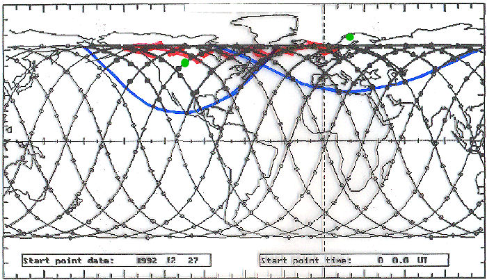
Eight out of thirteen orbits per day go through the oval. This figure clearly shows the need for a ground station Canada in order to cover as many passes through the oval as possible. Therefore, a receive-only station at Prince Albert in Saskatchewan (53.21°N, 105.93°W) was used. Of the 8 orbits per day that went through the oval Prince Albert could receive data during 7 and ESRANGE during 5 orbits. However, Prince Albert covered "better" passes through the oval than ESRANGE.
 Commands for transmitting data and for
switching on and off experiments were all transmitted from ESRANGE. The
satellite had a stored-command capability.
Commands for transmitting data and for
switching on and off experiments were all transmitted from ESRANGE. The
satellite had a stored-command capability.
A total of 140 minutes (270 MB) of data could be received at the two ground stations per day if the downlink data rate was 262 kbps. The radio link was able to support 524 kbps during passes over ground stations.
For reception S-band there were at least three antennas available, the largest of which had a diameter of 13 meters. Data rates up to 524 kbps were therefore possible. All receive antennas had auto-track capability.
The uplink antenna at ESRANGE was the 7 meter UHF antenna used for transmitting commands to sounding rockets and balloons and for receiving satellite telemetry. The output power at 449.95 MHz, the FREJA command frequency, was up to 400 Watts. The antenna could be program-steered or slaved to any receive antenna.
The FREJA Operations Center (FOC)
The operations center for the FREJA mission provided all
services necessary for the control and monitoring of the satellite. Its primary
function was to control and optimize satellite performance and to store and
protect the integrity of the downlinked telemetry data. Thus, its functions
were:
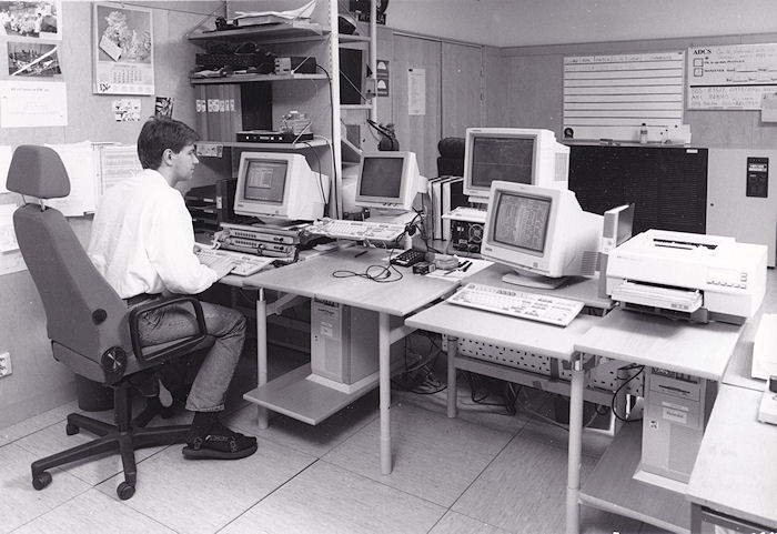
FOC was located within the TELE-X Satellite Control Facility (used for real-time control of the TELE-X geostationary communications satellite). FOC staff communicated with the science center by intercom and between FREJA passes the satellite operator conferred with the scientists face-to-face. The picture below shows satellite operator Anders Nilsson on-console in the Freja Operations Center.
The FREJA Interactive Science Center (FISC)
The science center was the interaction point between the
scientists using FREJA and the Operations Center. The most important functions
of FISC were to reduce telemetry data in near real time or to process stored
burst memory data, to display this data in a convenient form for the on-site
scientists and to allow rapid interaction between the scientists and the
experiments on board FREJA
FISC consisted of computers and other facilities provided by the scientists. SSC made available an interface to the Operations Center computers through which the scientists had direct command access to their experiments during passes over ESRANGE. FOC was transparent to such commands and only filtered the science command stream to make sure that no satellite-level commands were transmitted. FISC was located in the lobby of the TELE-X Satellite Control Facility. This lobby was divided into sections for each PI.
The Prince Albert Satellite Station
The
primary function of the Prince Albert ground station was to receive data from
FREJA as directed by the FREJA Operations Center and to store and protect the
integrity of the downlinked telemetry data and forward it to ESRANGE by parcel
mail. The largest antenna available at Prince Albert has a diameter of 26 meters
and a beamwidth of 0.36°. This antenna easily supported a 524 kbps data
rate.
Data Categories
During a pass over a ground station the
station collected data on hard disks
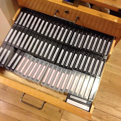 DAT tapes from Freja still kept in 2015 at the Space and Plasma Physics Group at the Royal Institue of Technology in Stockholm (KTH). |
 The F1 experiment on Freja was developed by the Space and Plasma Physics Group at KTH. Göran Olsson worked on its design. |
FREJA was launched (this video clip was compiled by Gudmund Johansson, a member of the Freja project team) at 0620:05 UT on October 6, 1992 (see picture below). FREJA was given the international designator 1992-64 A and the US Space Command catalog number 22161. The mass at launch was 255.85 kg and the on-orbit mass 214.0 kg. The initial orbit ranged between 601.0 km and 1756 km at 63.0° inclination. The initial nodal period was 108.97 minutes and the initial argument of perigee was 260°. The satellite is expected to decay from orbit due to atmospheric drag in >250 years.
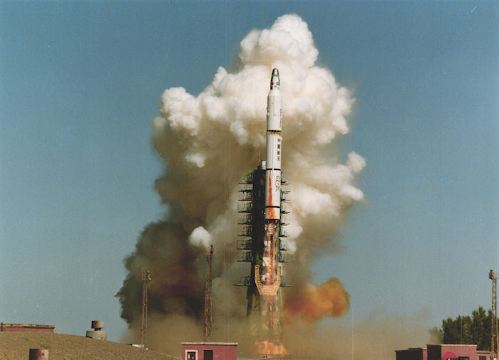
Freja
was launched at 0620 UT on 6 October 1992.
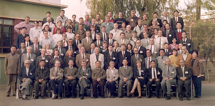
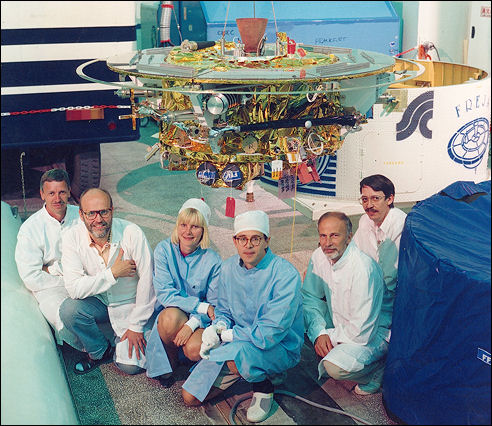
Traditional group picture
taken after the launch of Freja. Swedes, foreign partners and key Chinese
staff.
Orbit maneuvers
The Chinese CZ-2C launch vehicle put FREJA into an initial
213.7-317.4 km orbit at 63° inclination. This orbit was too low for a long
duration mission and much too low for any meaningful science investigations.
Therefore FREJA is equipped with two solid propellant rocket motors that were
used to raise both the apogee and the perigee. Before firing the motors the
satellite was also spun up to 50 rpm by small solid propellant rockets. The
firing of these rocket motors and other critical operations during the first
orbits were controlled by the on board computer. The actual time line for the
initial operational phase through the first ground station contact was as
follows:
| Event |
Time, UT |
| Lift-off |
06:20.05 |
| Freja separation (115.3°E, 18.44°N) |
06:30.01 |
| Spin up |
06:30.11 |
| STAR 13A |
06:56.59 |
| STAR 6B |
07:49.47 |
| Spin down |
07:51.47 |
| 400MHz transmitter ON |
07:52.33 |
| 400 MHz TX OFF |
08:15.33 |
Boom deployment operations
The
outer and inner sections of the stiff booms for the magnetometers were deployed
by stored commands over the Southern hemisphere on October 13 at 0210 UT and
0400 UT. Other science sensors were deployed on October 14 and the Stacer boom
for the Canadian Cold Plasma Analyzer came out on October 15.
Deployment of the three wire booms pairs to 10 m, 10 m and 5 m respectively was comple ted late on 22 October. Two pairs were deployed to 10 meters length per boom (i.e. 20 m tip to-tip) and one pair was reeled out to 5 meters (10 m tip-to-tip).
Changes in spin and attitude
The
satellite was then spun down to 10.03 rpm and maneuvered so that the spin axis
got close to the sun. On November 17, the spin rate was measured to be 9.97 rpm
indicating a slow decrease of the spin rate, probably caused by eddy currents
induced in the structure or some other damping mechanism. If needed regular
spin-up maneuvers can be performed to main tain the spin rate very
close to 10 rpm.
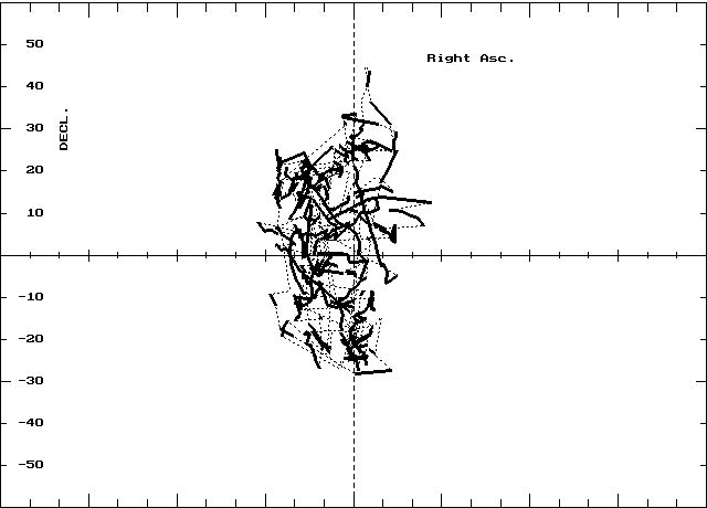
Since the
radius vector to the earth's center does not normally lie in the plane of the
wire booms there is a gravity-gradient torque acting on the spacecraft caused by
the long booms.
This torque causes a motion of the spin
vector. Between November 17 and November 18 the declination of the spin vector
changed +0.5°/ day and the right ascension -1.7°/day. The figure below
shows the motion of the spin axis relative to the sun during the first year of
operations.
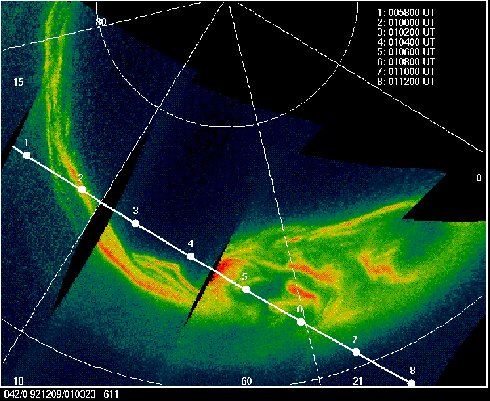
Science data collection
Science data taking operations started at full scale in
late October 1992. Data reception at the Prince Albert Satellite Station in
Saskatchewan, Canada, began on October 24. The two ground stations received
and distibuted about 400 MB of data per day. Data were distributed as DAT tapes
to PI:s and Col:s. So-called FREJA Summary Plots were generated at Esrange
and distributed via computer links in PostScript format. The image below
shows the aurura as seen by the Canadian F5 imager on Freja on 9 December 1992.
The track of the magnetic field-line footprint through the auroral arc is
marked.
A fter four successful years of operation (four times the intended lifetime) Freja ceased to respond to commands. This was discovered on Wednesday October 9, 1996. Pre-programmed commands switched on the transmitter for the last time at about 2030 UT on Monday, October 14, 1996. The cause of the loss of the command link was probably caused by radiation damage to a monostable multivibrator in both command bit synchronizers.
Freja has been operated from SSC's space operations base at Esrange, Kiruna. The primary mission ended June 30, 1995. Up until that date, all possible orbits were received from Esrange and the Canadian station at Prince Albert, Saskatchewan. Starting on July 1, 1995 only one pass over Esrange per weekday was received.
A large number of scientific papers about the results of the Freja mission have been written and a book with a collection of such appears, "The Freja Mission" has been published by the Kluwer publishing house.
The graph below has been computed using NASA's Debris Assessment Software. It shows that Freja till stay in orbit a few hundred years.