Pictures from a visit on 23 March 2012
Sven Grahn
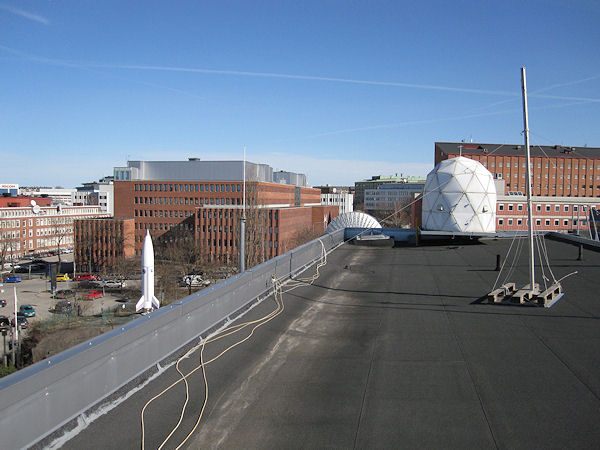
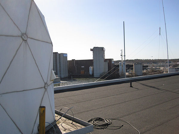
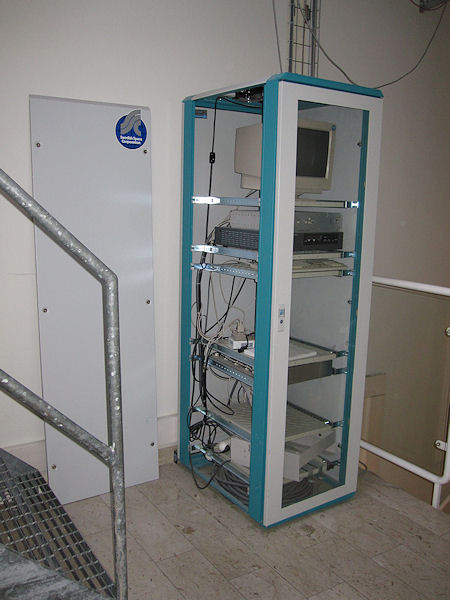
The ground station for Astrid-2 was established on the roof of the Swedish Space Corporation at Solna Strandväg 86, Solna, Sweden during 1998. Astrid-2 is the only satellite (so far) in the Swedish space programme that was not controlled from or used antennas at Esrange. Two important persons in this work were Klas Sjerling (RF systems) and Hans Ringstrand (computers, software and much else). The project manager for Astrid-2 was Staffan Persson. I was their boss as general manager of the Space Systems Division of SSC.
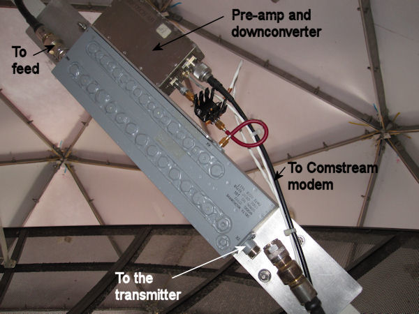
The station had an uplink to Astrid-2 on 2033.35 MHz which was frequency-shift keyed (FSK) and Bi-ø-L-coded. The data rate was 4.8 kbps. The station received data from the satellite on 2208.163 MHz which was BPSK-modulated and convolutionally encoded. The useful data rate was 128 kbps. The station block diagram is shown below.
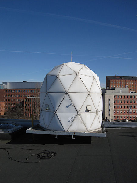
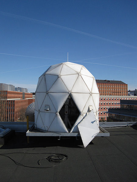
The station was used during the period 10 December 1998 (the day of launch) - 24 July 1999 (loss of contact). The station was maintained about another year, but as the hope of another Astrid mission faded the station fell into a state of decay. Ventilation of the radome was maintained for another year or so. When I took these pictures on 23 March 2012 (about 13 years after launch) there was a left-over soldering station and several other tools and parts on the floor inside the radome. The radome is in surprisingly good condition but there is some moisture mold on the lower part of the inside of it. The equipment inside the radome show no signs of mold or corrosion and there are practically no cob webs. Only wooden parts show signs of decay.
|
|
|
|
|
|
|
|
|
 To save money we decided to avoid buying a stabilized high-power DC power supply for the transmitter. Instead we used car lead-acid batteries (under the bench) and stan- dard chargers (to the right of the bench) to replenish the batteries between satellite passes. |
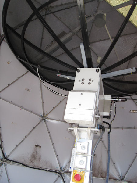
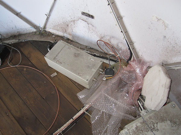 The white box contains the exciter, i.e. the low-power part of the uplink transmitter. It was modulated by the command signals from the control room. The exciter drove the power stage of the transmitter (see above). |
|
|
|
|
|
 .
.