Antennas on Soviet spacecraft
Sven Grahn
Interkosmos 16 platform
The small sun-pointing spacecraft
developed by Yuzhnoye in Dneipropetrovsk has an interesting antenna design
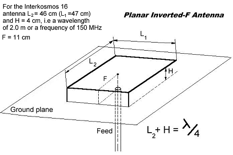
for what I think is the 180 MHz telemetry downlink. On the back of each
solar panel, there is a mesh mounted on insulators a few centimeters away
from the panel back. One edge of the mesh is grounded to the panel. A coax
feed the mesh with RF power as shown below. The reason for using a mesh
is that it is transparent to infrared radiation, a feature becessary to
radaiate heat from the solar panel. This antenna resembles a patch antenna.
It is a clever antenna. No rods needed, very simple manufacturing, takes
up very little room!

Bruce Blevins, Telecommunications
Team Leader at the Physical Science
Laboratory of New Mexico State University has helped identify the antenna
type as a "planar inverted-F antenna" described in the book "Analysis,
Design, and Measurement of Small and Low-Profile Antennas", Hirasawa and
Haneishi, Artech House, Boston, 1992." The figure below shows the resonance
condition. So, the estimated operating frequency is relatively close to
the observed signal at 180 MHz!

This kind of antenna can
be examined at a full-scale model of the Interkosmos-1 satellite displayed
at the National Museum of Science and Technology in Stockholm, Sweden.
That is the source of the dimensions in the figure above.
Small Ukraine Kosmos platform
Similar in design to the Interkosmos
16 platform, but with a different antenna for its main telemetry link,
there are several small satellites designed by Yuzhnoye. Instead of the
"Planar Inverted-F Antenna" described above it has a little loop antenna
with one side connected to chassis ground. The other end is fed via a coax
through the outer panel of the satellite

The length l has been measured
at a model on display at the Museum of Technology in Stockholm in July
1978. l=0.8 m. If this is half a wavelnegth, then the wavelength is 1.6
m. This corresponds to 187.5 MHz. This agrees rather well with observations
of PPM-AM telemetry near 180 MHz.
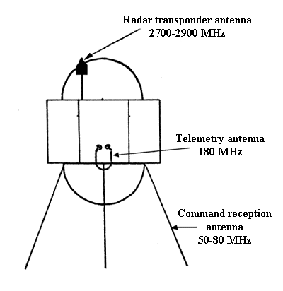
In addition to these antennas
there are two more antenna systems on this kind of platform as shown in
the figure below.

The command reception antennas
for 50-80 MHz in the figure above are made up of rolled-up pre-stressed
stell bands that form a tube when released. They can also be examined on
the Interkosmos-1 model at the National Museum of Science and Technology
of Sweden mentioned above.

 Back
to Space Radio Notes


