An analysis of the design of GRAB, the first
ELINT satellite
Sven Grahn
Contents
The U.S. has declassified
its first space-based ELINT system, GRAB. Details of this system have been
published on the web by the Naval Research Laboratory. My intention here is to
try to understand better the working principles of this system.
The first GRAB satellite
was launched by a Thor Able Star rocket on 22 June 1960 and was a piggyback
payload with the Transit-2A navigation satellite. The GRAB satellite (60-007B,
Space Command catalog number 0046) was placed in at orbit between 614-1061
km at 66.7 degrees inclination. The satellite weighed 19 kg. Its name in
the open domain was Solrad-1 and the telemetry frequency for its science
payload was 108 MHz. Later versions of Solrad used the then new 136-138
MHz band for telemetry. The second GRAB satellite was called Greb-3
and was launched with Transit-4A on 29 June 1961 and the transmission frequency
has been given as 136.2 MHz and 136.5 MHz. The GRAB system was later renamed
DYNO(2).
Soviet
radars targeted
The system is described as being
a transponder that picked up the radar signals from two Soviet radar systems,
Gage
and Token, and rebroadcast these directly to the ground. First,
let us determine what frequencies the Soviet radars used.
 In
(1) the Gage system is described as
an acquisition and the trtaadar used with the Yo-Yo missile control
radar for the early surface-to-air missile system SA-1 Guild. The
radar operated in the 3 GHz range with a 2 MW power output. The Yo-Yo radar
is described as a missile control radar that tracks more than two dozen
targets simultaneously with flapping beams used for tracking. Six antennas
which rotate cover 70 x 70 degrees. The system also operates in the 3 GHz
band (E-band) and also has 2 MW peak power.
In
(1) the Gage system is described as
an acquisition and the trtaadar used with the Yo-Yo missile control
radar for the early surface-to-air missile system SA-1 Guild. The
radar operated in the 3 GHz range with a 2 MW power output. The Yo-Yo radar
is described as a missile control radar that tracks more than two dozen
targets simultaneously with flapping beams used for tracking. Six antennas
which rotate cover 70 x 70 degrees. The system also operates in the 3 GHz
band (E-band) and also has 2 MW peak power.
 The
same source describes the Token radar as an early warning radar
with twin truncated wire mesh antennae similar to a widely deployed radar
code-named Barlock. In the early warning mode of operation the Token
radar had a range of 250-300 km with a 1 km accuracy. It operated in the
2.7-3.1 GHz range, had a pulse repetition frequency (PRF) of 375 pulses-per-second
(pps). The pulse duration was 1.6-3.1 microseconds. So, interestingly both
radars operated near 3 GHz. This means that the GRAB onboard receiver did
not have to cover a very broad frequency range, something that simplified
the design of the collection antenna.
The
same source describes the Token radar as an early warning radar
with twin truncated wire mesh antennae similar to a widely deployed radar
code-named Barlock. In the early warning mode of operation the Token
radar had a range of 250-300 km with a 1 km accuracy. It operated in the
2.7-3.1 GHz range, had a pulse repetition frequency (PRF) of 375 pulses-per-second
(pps). The pulse duration was 1.6-3.1 microseconds. So, interestingly both
radars operated near 3 GHz. This means that the GRAB onboard receiver did
not have to cover a very broad frequency range, something that simplified
the design of the collection antenna.
RF bandwidth
of the radar transmissions
The pulse width determines the
RF bandwidth necessary to pick up the most of the energy spectrum of the
radar. The bandwidth is 2/T, where T is the pulse width. So, for T=1.8-3.1
microseconds, we obtain a bandwidth of 650 kHz - 1.1 MHz. (The spectrum
of a radar signal is shown here) However
a bandwidth of a few kilohertz is sufficient to relay the basic PRF buzz
and the rotation scan rate of the antenna. So, the question arises whether
or not the radar signals were detected onboard with an AM detector and
then only a narrow band version of the baseband signal was allowed to modulate
the downlink transmitter.
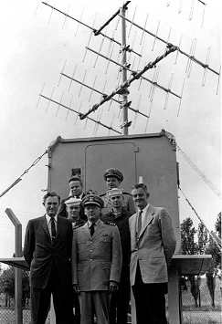 Downlink
from the GRAB satellite and its receiving antenna
Downlink
from the GRAB satellite and its receiving antenna
First, let us look at the downlink
from the satellite. The approximate frequency band can be inferred from
the picture on the right (from NRL's web site) showing the receiving hut
placed in friendly territory just outside the borders of the USSR. Even
if the perspective distorts the proportions, it seems that the antennas
array could operate somewhere in the 130-200 MHz region.
Interestingly the antennas
are linearly polarized. If the satellite transmitting antennas were circularly
polarized using a linear antenna on the ground would mean losing 3 dB of
signal. If the satellite transmitted linearly polarized signals, the rotation
of the polarization of the wave through the faraday effect would have caused
regular deep fading of the signal. Most probably the satellite carried
a turnstile type antenna system that generated a circularly polarized wave.
Another interesting feature
of the receiving antenna is that it was mounted at a fixed elevation and
rotated only in azimuth. This is a wise choice if one wishes the system
to be simple. Satellites are mostly near the horizon!
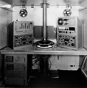 Receiving
and recording equipment - looking inside the hut
Receiving
and recording equipment - looking inside the hut
The picture of the inside of
the hut is very interesting. The first thing one notices is the wheel between
the two racks for hand-steering the antenna in azimuth.
The second thing that strikes
you at the first glance are the two Collins R-390 shortwave receivers.
These are certainly not intended for use beyond about 30 MHz, so to be
used with the antenna system on top of the hut a frequency converter is
needed.
Secondly, the IF bandwidth
of the R-390 is only some tens of kHz, so this means that, probably,
the signal from the satellite was a detected, narrow-band version of the
radar pulse train with only a few kHz bandwidth. In this way the signal
could easily be recorded as an audio signal on the reel-to-reel tape recorder
in the right-hand rack. Possibly the first IF at 455 kHz could be pulled
out of the receiver, but its bandwidth can still not be recorded by the
tape deck.
The device on top of the
left R-390 looks like an old-style pulse counter. It could possibly also
be some kind of display of telemetry from the GRAB satellite. But
perhaps an even better hypothesis has been proposed by Pete McCollum (check out
his website http://militaryradio.com/spyradio/ and
http://militaryradio.com/spyradio/intercept.html):
"I believe that device is a time-of-day digital clock. It uses a vertical
numeric display, similar to early HP frequency counters, such as the HP-522B for
example. Note that the length of the columns is just right for displaying up to
"23:59:59".
Antennas on the spacecraft
The figure below shows where
I think the radar recption antennas are located on the GRAB spacecraft.
References
-
The International
Countermeasures Handbook, second edition 1976-77, edited by Harry F Eustace.
-
E-mail
message from space reconnaissance historian Dwayne Day, 18 March 2001.

 Back
to Space Radio Notes
Back
to Space Radio Notes