Gemini
Radio Systems
Sven
Grahn
The Gemini
spacecraft was a huge step forward over the Mercury spacecraft. The
level of
sophistication is well reflected in the unusual reliability of this
spacecraft
despite its complex mission and rapid launch sequence. However, its
radio
systems were a compromise between sophistication and speed of
development.
There was not enough time to develop something like the Unified S-Band
system
used on Apollo and the Space Shuttle. Geminiís radio systems therefore
included
separate equipment for each function.
The table
below is mostly based on (1) but also on
information from COSPAR Information Bulletins. The Gemini-6 and
Gemini-7
frequencies come from an old issue of the COSPAR bulletin. These
frequencies
were not mentioned for any other Gemini spacecraft. In (1) there is no command frequency given for the Gemini
itself but only for the Augmented Target Docking Adapter. I have
assumed that
the same frequency band is used for the manned Gemini spacecraft itself.
|
Purpose |
Modulation |
Power, Tx |
Data rate
kbps |
Frequency |
|
Acquisition
aid |
CW |
200 mW |
- |
246.3 MHz |
|
Recovery
beacon |
? |
50 W pulses |
? |
243.0 MHz |
|
UHF Voice
Tx/Rx |
AM |
3 W |
- |
296.8 MHz |
|
HF Voice
Tx/Rx |
AM |
5 W |
- |
15.016 MHz |
|
Real-time
telemetry |
PCM
(NRZ)-FM |
2 W |
51.2 |
230.4 MHz |
|
Delayed
time telemetry |
PCM
(NRZ)-FM |
2 W |
112.6 |
246.3 MHz |
|
Back-up
telemetry |
PCM
(NRZ)-FM |
2 W |
51.2/112.6 |
259.7 MHz |
|
Gemini-6 TM |
PCM
(NRZ)-FM |
? |
? |
249.2 MHz |
|
Gemini-7 TM |
PCM
(NRZ)-FM |
? |
? |
249.3 MHz |
|
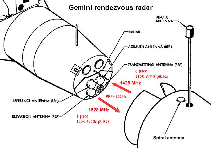
Rendezvous
radar Tx |
Pulse |
1150 W |
250 Hz PRF |
1528 MHz |
|
Rendezvous
radar Rx |
Pulse |
1150 W |
250 Hz PRF |
1428 MHz |
|
C-band
radar Tx |
Pulse |
0.5 or 1
kW |
- |
5765 MHz |
|
C-band
radar Rx |
Pulse |
- |
- |
5690 MHz |
|
S-band
radar Tx |
Pulse |
? |
|
2910 MHz |
|
S-band
radar Rx |
Pulse |
- |
|
2840 MHz |
|
Digital
Command System Rx |
PSK |
- |
|
406-450 MHz |
The orbital
C-band transponder had a 1 kW output, while orbital transponder
transmitted at
500 W. The command receiver could handle Real Time Commands (RTC) or
Stored
Program Commands. The RTCs triggered nine relays.
The Agena target vehicle had two redundant telemetry
transmitters operating on 246.3 MHz with a +/-150 kHz deviation and 2
watts RF
ouput. The command receiver of the target used a frequency in the
406-450 MHz
range. The C-band transponder of the target operated on the same
frequencies as
the Gemini spacecraft itself.
Telemetry from the ATDA was picked up in Florida on
246.3 MHz by my friend Richard S Flagg when he was a member of the
University
of Florida Student Tracking Station in Gainesville. (Click here to listen). The Student Tracking Station also managed to
receive voice from
the Gemini spacecraft. Listen here for a short transmission
from
Gemini-9 on 296.8 MHz where the range and range-rate to the ATDA target
are
called out..
The first
space based radar
The radar
receiving antenna system consisted of three dual spiral antennas 16.5
cm in
diameter. The receiving antennas, along with the transmitting
antenna,
form a square array 0.82 wave lengths apart. There were three receiving
antennas: the azimuth antenna, the elevation antenna, and the reference
antenna. The elevation and azimuth antennas were rotatable. The
transmitting
antenna and the reference antenna do not rotate. The spiral antennas
were
raised a quarter wavelength above the radar faceplate and they had a
circumference
of 2.4 wavelengths, i.e. 52 cm. The reference antenna was used
alternatingly
with the azimuth an elevation antennas to determine the bearing to the
target. The terms
azimuth and elevation may seem confusing, but they are used in the Gemini Familiarization Manual. When the spacecraft
was
oriented along the local vertical and with its longitudinal axis along
the
orbital velocity vector they were equal to yaw and pitch, of course.

There is a reason why the transponder transmits a 6
microsecond pulse in reply to a 1 microsecond pulse. The signal on the
two
horizontal and subsequently the two vertical receiving antennas must be
present
for an interval long enough to compare their phase relationships.
The method that was used to measure bearing was based
on the fact that the transmission lines from the three receiving
antennas were
wired so that the RF voltage induced in the azimuth and elevation
antennas were
180 degrees out of phase with the RF voltage induced in the reference
antenna,
if the target transponder was on the radar boresight axis. The sum of
the
compared voltages was zero. If, however, the target was off-boresight,
e.g. in
azimuth, the path lengths to the reference antenna and to the azimuth
antenna
will be different. Therefore, the phase difference between the RF
voltage
induced in the two antennas will not be 180 degrees. As a result, there
was not
complete cancellation as before. An error voltage proportional to
the displacement
from the boresight axis will result.
The method used to null out the error voltage
constituted the interferometer method of angular measurement. The
method
depended on a peculiarity of a spiral antenna. The spiral antenna
shifts the
phase of the RF voltage induced in it as it is rotated about its
center.
Therefore the 180-degree phase difference between the azimuth and
reference
antennas could be restored by rotating the azimuth antenna. The amount
of
azimuth antenna rotation required to restore the null is proportional
to the
target displacement in azimuth. The error voltage was used to drive a
motor
which rotated the antenna until the error voltage was again zero.
The antennas on the Agena target are both dipole and
helices and the generate an antenna pattern almost without nulls. See figure
here.
Communications
antennas

The HF antenna was 3.9 meters long
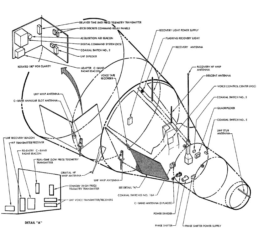
when extended in orbit. The C-band transponder antenna system for
ascent
and re-entry used three helical antennas on the forward end of the
cabin. A
phase shifter was used to make the antenna pattern vary and fill out
all voids.
The orbital C-band transponder used an annular slot antenna mounted on
the
equipment section of the adapter. It is flush-mounted with the skin as
can be seen
in the figure above.
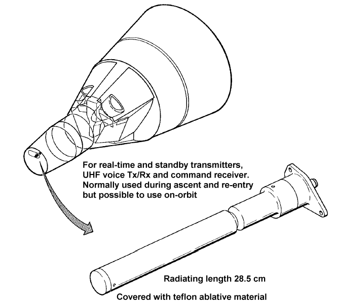
Detail
of UHF stub antenna
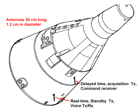
Location and
purpose of UHF whip antennas

