 Frequency
division multiplex telemetry - a few fundamentalsFrequency
division multiplex telemetry - a few fundamentals
Frequency
division multiplex telemetry - a few fundamentalsFrequency
division multiplex telemetry - a few fundamentalsThe basic operation of a frequency-division multiplex telemetry system is illustrated in the figure below. The measurement signals from transducers modulate "subcarrier" oscillators tuned to different frequencies. The output voltages from the subcarrier oscillators are then summed linearly. The composite signal is used to modulate the downlink transmitter.
In the receiving station the composite signal is available at the output of the receiver demodulator which is then fed to bandpass filters that are tuned to the center frequencies of the subcarrier oscillators. The outputs from the filters are the demodulated and the original transducer signals are recovered.
All types of modulation can be used for both the subcarrier oscillators and the prime carrier. The transmission system for frequency division multiplex systems is designated by first giving the modulation for the subcarriers and then the prime carrier. Thus FM/AM would indicate a frequency-division multiplex system in which the subcarriers are frequency modulated and the prime carrier is amplitude modulated by the composite subcarrier signal.
The most commonly used frequency-division multiplex system is FM/FM. Standards were established in the U.S: for FM/FM systems shortly after World War II and they later became known as the Inter-Range Instrumentation Group (IRIG) standards. The FM/FM standard established the center frequency for subcarriers and how much bandwidth each subcarrier can occupy. the table below shows the IRIG FM/FM subcarrier channel assignments.
The most noteworthy variants frequency-division multiplex systems used in addition to FM/FM are FM/PM and SS/FM (for Single-Sideband/FM). An FM/PM system was used in the early days of the U.S. space program under the name of Microlock, because phase-locked receivers were used to acquire and detect the main carrier. The early Explorer satellites and Pioneer probes used this system.
However, the amount of information transmitted in these early systems was very limited. By using single-sideband subcarrier signals much more data could be compressed in a narrow bandwidth and the SS/FM systems were used in early Saturn 1 flights.
 The
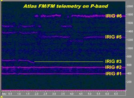
figure on the right shows about seven seconds of FM/FM telemetry from
an
Atlas rocket launched from Cape Canaveral in the early 60's. (The
recording
was made by the University of Florida Student Satellite Tracking
Station
and has been made available to me by my friend Richard Flagg).
The
figure on the right shows about seven seconds of FM/FM telemetry from
an
Atlas rocket launched from Cape Canaveral in the early 60's. (The
recording
was made by the University of Florida Student Satellite Tracking
Station
and has been made available to me by my friend Richard Flagg).
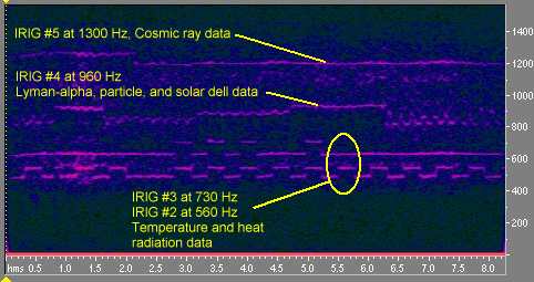
The carrier frequency was in the P-band region, i.e. 215-260 MHz. The figure shows five subcarriers and their behavior at the time of booster engine separation. We can easily spot IRIG subcarriers 1, 2, 3, 5 and 6.
It seems that IRIG 3 disappears at 1.9 seconds into the recording. By clicking on the spectrogram you can hear a sound file with these signals.
Normally, the outputs from the subcarrier demodulators in the receiving station were applied to banks of meters or to multi-channel strip-chart recorders. These recorders were either of the type with ink pens writing on moving paper, ultra-violet light beams drawing traces on UV-sensitive paper or so-called Sanborn recorders which used heat pens (hot wires which made black lines on special paper). I have myself been crawling on the floor at the Swedish rocket base Esrange analyzing strip-chart recordings from a sounding rocket as they rolled out of the recorders in real time!
In the early days of telemetry Analogue Time-Division Multiplex systems were used in conjunction with frequncy-divsion multiplex systems. A very common type of time-division mutiplex was the Pulse-amplitude modulation (PAM) system. The output of the commutator in such a system is a series of pulses, the amplitudes of which correspond to the sampled values of the input channels from the transducers. At the receiving station the process is reversed. The demodulator output from the receiver is passed through a decommutator that produces outputs corresponding to the sampled measurement signals.
 The
pulse-amplitude waveform may take several forms as can be seen below.
The
principle difference lies in the duty cycle of the pulse. In the figure
on the right the top diagram shows a 100% duty cycle system while the
lower
diagram shows a 50% duty cycle system.
The
pulse-amplitude waveform may take several forms as can be seen below.
The
principle difference lies in the duty cycle of the pulse. In the figure
on the right the top diagram shows a 100% duty cycle system while the
lower
diagram shows a 50% duty cycle system.
The length of time necessary to sample all channels is called the "frame time". In order to identify the channel corresponding to a sample at the receiving station, it is necessary to provide frame synchronization.
Several different methods can be used to designate the beginning of a frame. The method illustrated on the right consists of forcing several consecutive channels to a level below the minimum allowable data value. Since drifts and non-linearities cause errors, it is also common practice to transmit calibration pulses as shown in the figure.
Bill Obenauf, who worked at Lockheed with Agena-based spacecraft recalls "the commutators which were used to monitor 30 or 60 voltages (temps, positions, etc.) and fed to one of the higher frequency oscillators. The output at the ground station was a complex square wave, recorded and read by hand using a Gerber Scale. It was a cumbersome task. The early Agena Satellites used a vacuum tube version of FM/FM Telemetry. I worked on calibration of these oscillators in the 1950's at Lockheed in Van Nuys, California."
In addition to the primary time- and frequency-division multiplex techniques described here, there are cases in which these techniques are combined. One of the most commeon combination has been that of PAM and FM/FM to form PAM/FM/FM. In this case a PAM time-division multiplex signal is used to modulate an FM/FM subcarrier. Several other subcarriers may also be modulated with separate PAM signals. Usually the higher frequency subcarriers are used for PAM signals and the lower frequency subcarriers are used for direct measurments.
As an example, the PAM
sampling
rate for IRIG channel 5, with a subcarrier center frequency at 1300 Hz,
is 10 samples per second.
The picture below shows a piece of the telemetry transmission from Explorer-7. Click here (25 kB mp3-file)or on the spectrogram to hear the signal.