Finally on the air on S-band
A
continuing account
Sven Grahn
·
September 16, 2007 - tracking
Foton-M3
·
Putting up the 3.5-turn
helix
·
October 1, 2007 -
tracking Sweden’s orbital observatory Odin
·
Tracking the HEOs on
2242.5 MHz
·
October 15, 2007 – taking
the next step, ordering and taking delivery of the SDR-14
·
October 15, 2007
– Getting the first spectrograms and suspecting the sensitivity is not very
good
·
October 16, 2007 –
Measuring two helix variants and the circular horn with a network analyzer
·
October 17,
2007 – Measuring the gain of the pre-amp, that explains some of the problems
·
October 17, 2007 –
Measuring the attenuation of coax cables, replacing the crucial one
·
October 23, 2007 –
Sensitivity still not OK, reading the manual and finding that the system lacks
gain
·
October 25,
2007 – Getting an extra amplifier
·
October 26,
2007 – Trying the new system, getting much better results
·
October 26, 2007 – Tuning the AIM
·
October 26, 2007 –
DMSP B5D2-8 command-on
·
October 27 and 28,
2007 – Tracking Chang’E
·
October 28, 2007 –
Another go at the AIM satellite
·
October 29, 2007 – Chang’E picked up just before another
raising of the apogee and picked up an unknown
In September 2007 I
finally took a deep grab into my pocketbook and bought an AR8600 Mk2 (did not
have the guts to buy the AR5000) that covers everything almost from DC to 3 GHz
and started to retire all my old radio gear. I had tried S-band tracking two
summers ago, when I got the Okos with a WLAN dish (see “Tracking Oko
from Sweden”). But that effort used a down-converter from S-band that is
very prone to frequency drift and the IF receiver - an old ALINCO DJ-X10, the
battery of which did not charge properly. All in all, it was a temporary effort
that I did during the summer at my country cottage. I needed to do something
more permanent at home in town – in Sollentuna near Stockholm.
September
16, 2007 - tracking Foton-M3
 By the time I got the receiver delivered I had not yet
built the 3.5-turn helix that everyone seems to use. However, at the country
cottage I had an S-band horn (see drawing) made out
of brass that I built many years ago from a design that I got from Dick Flagg.
Over a week-end I brought the AR8600 to the country house and tried to receive
the newly-launched Foton-M3, which was transmitting on 2208.163 MHz. That
transmitter is part of the Telescience Support Unit (TSU), a TT&C system
that serves the ESA microgravity experiments aboard the Foton. The transmitter
is phase modulated with an index that leaves some power in the carrier.
By the time I got the receiver delivered I had not yet
built the 3.5-turn helix that everyone seems to use. However, at the country
cottage I had an S-band horn (see drawing) made out
of brass that I built many years ago from a design that I got from Dick Flagg.
Over a week-end I brought the AR8600 to the country house and tried to receive
the newly-launched Foton-M3, which was transmitting on 2208.163 MHz. That
transmitter is part of the Telescience Support Unit (TSU), a TT&C system
that serves the ESA microgravity experiments aboard the Foton. The transmitter
is phase modulated with an index that leaves some power in the carrier.
My employer, the
Swedish Space Corporation, has built the system and our ground station at
Esrange in Kiruna was commanding and receiving it. The spacecraft would pass to
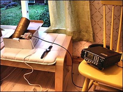
the north of me, so I put the horn looking out the upstairs window to the north
and at 1709-1711 UT on 16 September 2007 I was rewarded by a strong carrier
with extremely strong Doppler shift. Foton-M3 was in a really low orbit. The
picture below illustrates the receiving set-up - Yet another temporary rig (see
picture on the right)!
The horn turned out
to have a very wide beam (perhaps 90 degrees total cone angle) and I only had
to move it once to catch the pass. To the east there is a high stand of fir
trees and the signal was thoroughly attenuated by them. The polar plot shows the motion across the sky on the
next pass. At the green dot the spacecraft passed behind the trees. The signal
strength was impressive and the AR8600 S-meter climbed five or six steps up its
ladder, I brought the horn to town and was able to track the Foton from our
atrium.
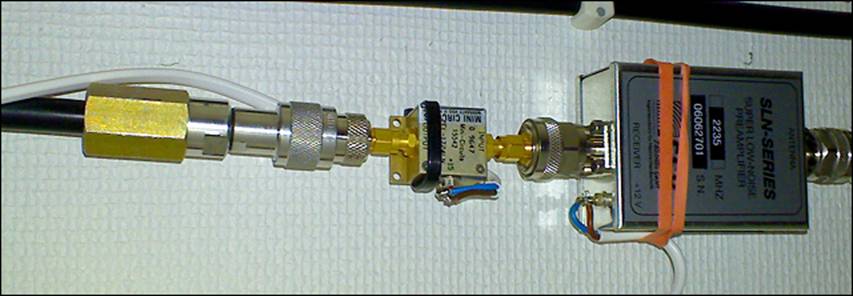
Putting up
the 3.5-turn helix
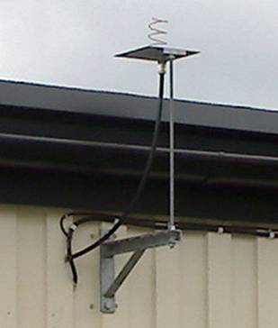
Now it was time to
turn to the problem of putting up the little helix at home. I have small
antenna pole on the side of our single-level house, but it is a few meters from
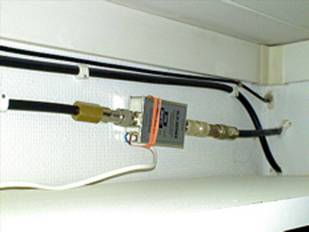
the radio shack. However, I decided to put the helix on a little bracket as
close to the shack as possible and also decided to put the pre-amp (NF=0.5 dB)
just where the coax enters the shack near the ceiling. The coax between the
pre-amp and the helix is 0.8 meters long adding a few tenths of a dB to the
noise figure, bu keeping the pre-amp warm and dry out in the open is a
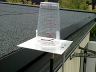
non-trivial task. I have decided to use this compromise for the time being.
Just as an experiment I bought some plastic beer mug at the local supermarket
and put on the helix as a “radome”. The helix is just made according to the
standard recipe but not yet checked with a network analyzer – work to be
performed soon.
|
It is hard to make
the coax shorter! |
The “beermug
radome” |
The “pre-amp
compromise” |
October 1,
2007 - tracking Sweden’s orbital observatory Odin
Once I had the helix
up I wanted to pick up Odin (cat nr 26702), a satellite the development of which
I had helped start in 1990 and which I had overseen when I was the head of the
Space Systems Division of the Swedish Space Corporation during the period
1993-2001. It is a great satellite of which I am immensely proud and which has
made great discoveries. It carries an S-band transmitter that is supposedly on
2208.163 MHz and it is phase-modulated. The spacecraft has separate
transmitters and receivers and there is no coherent transponder. The
transmitter is switched on by stored commands in the spacecraft computer. The
ground station usually operates automatically. Odin was easy to pick it up as
it passed straight over Stockholm on 1 October 2007. I noticed immediately that
the little helix has no gain whatsoever below 30 degrees elevation. The signal from
the spacecraft vanished very quickly when the spacecraft passes beyond this
limit. So the helix has a beam with a total width of 120 degrees. I also
noticed that the doppler-shifted frequencies of the transmitter at AOS and LOS
were not symmetrical around the nominal frequency 2208.163 MHz. On 2 October I
made a Doppler plot and it was obvious that the
Odin center frequency is near 2208.135 MHz. I called the Odin control center at
Esrange to find out what they thought. The lead satellite operator pointed out
that the transmitter temperature nowadays is about +40 C while the nominal
frequency was measured at room temperature. That may explain the frequency
difference.
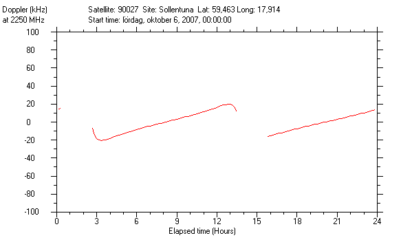
Tracking the
HEOs on 2242.5 MHz
Low orbit satellites
pass very quickly and are rapidly Doppler-shifted. Therefore without a spectrum
monitoring system, they require much attention to catch, so for the beginner
the Highly Eccentric Orbit objects that transmit on 2242.5 MHz are an easy
target. The behavior of their signals is counter-intuitive after having been
used to track low-orbit satellite. The first time I tuned the region around
2242.5 MHz I immediately noticed a carrier about 18 kHz below the nominal
frequency and one about 20 kHz above. Soon the higher frequency carrier
disappeared. The lower frequency carrier then gradually crept up in frequency
during 8 hours or so until it too disappeared at about + 20 KHz when a new
carrier appeared at about -18 kHz. And this is the behavior normally observed.
Increasing Doppler is of course the result of the satellites ascending to
apogee and then coming down. As the do this the range rate vis-à-vis me
increases from a positive value to a negative value. To understand the motion
of these strange U.S. spacecraft let us plot the motion of one of these
satellites during 6 October 2007, in this case the object known as 900027.
(1177-39170 km, i=62,8 perigee argument=270 deg),
The Doppler trace
with “hooks” is the one that comes more than 30 degrees above my horizon.
However, the “hooks” usually appear below 30 degrees elevation, so I will not
hear them.
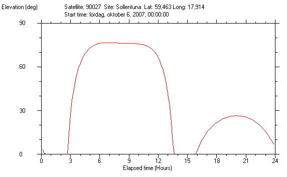
The figure below shows that on the “European Loop” the
spacecraft is more than 30 degrees above my horizon for more than 10 hours!
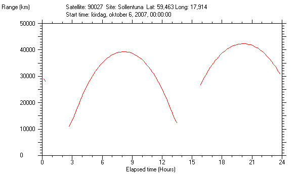
The range vs time plot reveals the reason for the
Doppler plot.
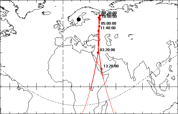
The ground trace is fascinating. The spacecraft
“hovers” over 41 E for more than six hours. Moscow happens to be located at
almost 38 E.
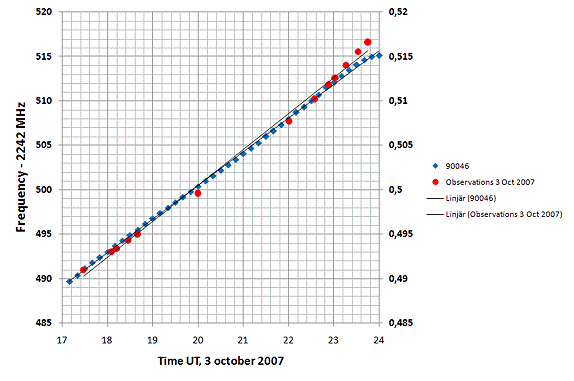
I spent some time
recording the Doppler frequency on 3 October 2007 and matching with simulated
Doppler data from the known fleet of HEOs (90004, 90020, 900025, 90027, 90028, 90046).
The match with object 90046 assuming a center frequency of 2242.498 MHz was the
best – but clearly the element set for 90046 was not perfect.
October 15, 2007 – taking the next step, ordering and
taking delivery of the SDR-14
I finally gave in and decided to spend 1000 $ on the Software Defined
Receiver, SDR-14, made by RFSPACE. I sent the order by e-mail on 2 October and it
arrived on 15 October. I came home in the afternoon and found it in a huge
plastic box with a tight-fitting lid that I had left for FedEx to drop it in. I
had the device up and running in 30 minutes with my old Dell laptop. The
bewildering array of settings obviously needed experience to master, but I immediately saw the carriers of a couple of DMSP satellites on the
“waterfall” display..
October 15, 2007 – Getting the first spectrograms
and suspecting the sensitivity is not very good
I tuned around to various
S-band frequencies and certainly saw signals, while from other satellites I got
nothing. I particularly tried NASA’s AIM satellite that puts out a nice
broadband signal. I tried that frequency and watched the waterfall. At first it
seemed there was nothing, but after close scrutiny of the image I could see a
broadband weak noise increase doppler-shifted across the display (see below).
But this looked nothing like that recorded by PJ Marsh. My
system clearly suffered from a sensitivity problem.
October 16, 2007 – Measuring two helix variants and
the circular horn with a network analyzer
I realized that to be
sure that I had a good receiving system, I needed to check out all the
components and I was able to get my employer, the Swedish Space Corporation, to
borrow one (Rohde &
Schwarz ZVL) for a week (thanks Mikael!). I started with two helices that I
have made and the horn used for Foton-M3. The helix made exactly as per the
instructions (here) was not
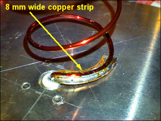
super-good. The return loss was 7 dB. I had made another one with a copper
strip soldered on to the first quarter-turn of the helix. It worked much better
and has about 15 dB return loss (see below).
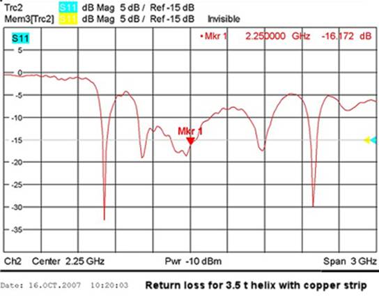
The circular horn
also displayed about 15 dB of return loss. Not fantastic, but good enough for
now. I decided to retire the original helix and put up the new one.
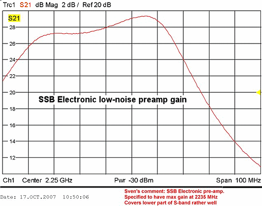
October 17, 2007 – Measuring the gain of the
pre-amp, that explains some of the problems
The next step was to
bring the pre-amp, the super-duper unit from SSB Electronic to SSC for analysis
with the network analyzer. It showed that the amplifier performs really well
for the lower part of S-band, but is really lousy for the upper 25% of the
band. This, obviously is part of the explanation for the very meager signals
from the AIM satellite. Its peak gain certainly agrees with the manufacturer’s
data, which says that peak gain is 29 dB. Apart from the fantastic noise figure
(0.5 dB) the pre-amp is not perfectly suited for covering the whole band.
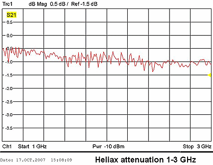
October 17, 2007 – Measuring the attenuation of coax
cables, replacing the crucial one
The coax between the
helix and the preamp was a standard RG214 with a connector inside the house
that I had to solder in a very awkward position,s o I feared that it was lossy.
However, I had salvaged some nice coaxes (Andrews Heliax and Suhner) from a
decommissioned ground station at the Swedish Space Corporation, so I brought
them to the Swedish Space Corporation for measuring the loss. The network
analyzer seemed to have some internal reflections, but the loss came out for
both cables as 0.8 dB for the Heliax and about 1.2 dB for the Suhner cable, I
put the Heliax between the helix antenna and the preamps. The Andrews Heliax
connectors are very big, so I had to drill a 25 mm (1 inch) hole in the wooden
wall of the house instead of a 10 mm hole!
October 23, 2007 – Sensitivity still not OK,
reading the manual and finding that the system lacks gain
I was worrying that
there was no noticeable increase in noise level when turning the preamps on.
Could it really be that the preamps were not loud enough to exceed the noise of
the AR 8600 Mk2 itself. I consulted the handbook and read to my surprise (other
specs say 2.5 uV) that the receiver has a sensitivity of 10 uV at 12 dB
SINAD using NFM (12 kHz at - 6dB point). Let us assume that the NFM noise
bandwidth is 15 kHz. Using these data in the little calculator below you get a
NF of 33.5 db (650,000 K).
http://www.vk1od.net/sc/RxSensitivityCalc.htm
This may not be
entirely correct, there is also the effect of the FM demodulator, but anyhow
the noise temperature at the input is very high. What kind of preamp gain is
needed to exceed that? If the receiver NF is 30 dB then it is wonder it is hard
to beat the receiver noise! Dick Flagg commented on these numbers:
“… The effect of preamp gain is
then very, very important. I did a few calculations as follows for a
system like yours with a 0.5 dB cable in front
of a 0.5 dB NF preamp driving a 1 dB cable to a receiver with a 30 dB noise
figure. I varied the gain of the preamp and calculated the receiving system
noise figure and temperature referenced to the terminals of the antenna.
G = 10 dB, NF= 21dB, T=41000
G=20 dB, NF = 12 dB, T=4168
G=30 dB, NF = 4.26 dB, T= 484
G=40 dB, NF = 1.46 dB, T= 116
As you can see you really need lots of gain to come anywhere near getting the
benefit of that very low preamp noise figure. Even more gain than 40 dB
would help. But I worry about so much gain without bandpass filtering.
Particularly with that MiniKits preamp which is probably broad as a barn.
It may be necessary to put a bandpass filter between the good preamp and the
line driver MiniKit…”
October 25, 2007 – Getting an extra amplifier
I realized that I
need an extra amplifier with about 20 dB gain, so I ordered an assembled
MiniKits EME103 pre-amp, but being a bit impatient I hit upon another idea. I
asked the an engineers at the Swedish Space Corporation if he had any S-band
amplifiers laying about. And, in a “electronics candy box”, Anders found two
MiniCircuits amplifiers (ZEL-1724LN), one used and one unopened in the original
antistatic plastic shipping bag. I got the used one on “loan” from the “candy
box”. It is a remarkable piece of hardware (1700-2400 MHz, Gain=23 dB, NF=1.3 dB)
but at a remarkable price ($275). Thanks for the help, Anders.
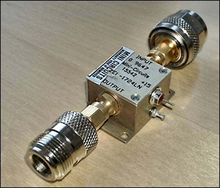
I hooked the new
preamp up directly after the SSB Electronic preamp (see below) and now a
distinct increase in noise could be noticed when turning on both preamps.
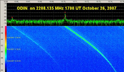
October 26, 2007 – Trying the new system, getting
much better results
Here are a few
examples of what 20 dB extra gain would do. For example, the Swedish Odin
satellite had just looked like a single line across the waterfall. Now there
was more detail.
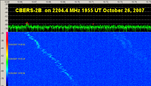
I also tried some
other birds, like CBERS-2B that PJ Marsh has shown to have a badly fluctuating
carrier. Is it broken? This is what I found:
I also was able to
pick up satellites on 2230.0 MHz that I had not succeeded with before. Cosmo-Skymed 1 was visible on the
waterfall at 1725.30-1734.55 UT, almost
10 minutes! At AOS the elevation was 6 degrees and a LOS the elevation
angle was 9.6 degrees. What happened to my rule that nothing is received below
30 degrees elevation? Well, this satellite certainly punched through that
limit. Also saw Metop-1 on 2230 MHz, but it was much weaker that Cosmo-Skymed
1. Envisat on 2225.0 MHz also visible, but it is a weak signal too.
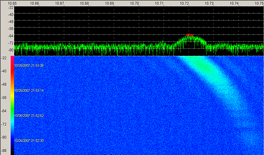
October 26, 2007 – Tuning the AIM
In the evening of 26
October I finally got the chance to see how good the improved system really was
and a few minutes before midnight local time I finally received the AIM
spacecraft. A marked improvement over the spectrogram from 15 October could be
seen (see below).
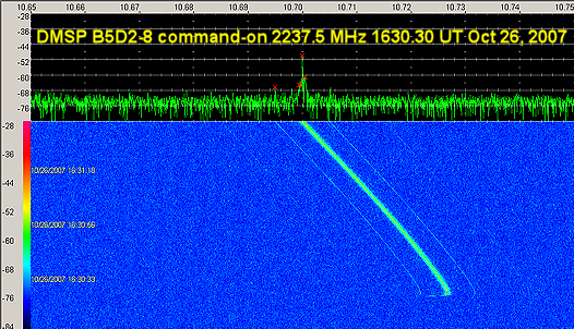
October 26, 2007 – DMSP B5D2-8 command-on
While tuning around
at random I kept the receive for a while on the DMSP housekeeping channel
2237.5 MHz. When I looked at it again I saw the strange shape below. The
transmitter was commanded on and it is possible to see how the transmitter
frequency quickly stabilized. But who commanded it on? Was it a ground station
or the spacecraft computer? It turned out that the spacecraft was DMSP B5D2-8.
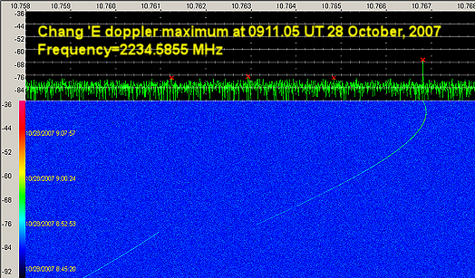
October 27 and 28, 2007 – Tracking Chang’E
When I switched on
the receiving system in the morning
(local time) on 27 October 2007 I had little hope of picking up anything
from the Chinese lunar probe Chang’E. The elevation above my horizon would
barely touch the 30 degree lower limit of my helix coverage. But I immediately
picked up a weak carrier and set the
SDR-14 to move really slowly so that
could get a good overview of the Doppler curve. I had to do gardening
work (cutting a high hedge) during the hours before noon, but when I came into
the house at 0920 UT after finishing the hedge work I saw that there had been a
frequency shift, a Doppler maximum and Loss-Of-Signal. I had run predictions
for Doppler shift and elevation angle using the original element set for
Chang’E (actually a secondary object but it had roughly the same orbit as the
moon probe) and those predictions showed no Doppler maximum or setting below my
horizon before 1000 UT. Clearly, if this was Chang’E, the orbit must have
changed. I logged into Space-Track and found that this was indeed so. A simulation
with the new orbital elements confirmed that I had indeed seen Chang’E (read
more here). The spectrogram
below shows the Doppler maximum on 28 October 2007.
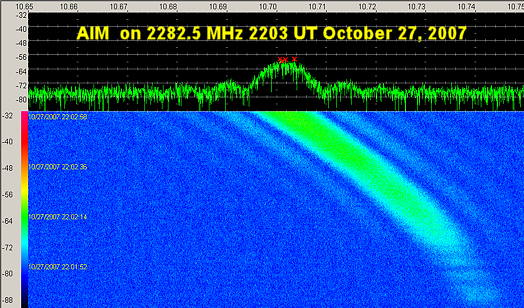
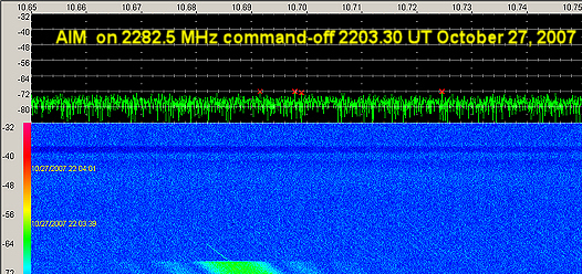
October 28, 2007 – Another go at the AIM satellite
I tried AIM again at
midnight 27/28 October 2007 and I received a really nice spectrogram (see
below) from AIM then restarted the waterfall, only to hear the noise from the AR
8600 go up (the AIM signal silenced the AR 8600 wideband FM detector) and saw
the signal on the computer screen vanish (see second spectrogram below) – sort
of. The downlink was commanded off, but from where?
below is the
command-off. Strange to see that there was a carrier a while after the wideband
signal disappeared and there is some residual weak wideband stuff even after
the carrier had disappeared. I tried tuning around to see if there had been a
change in operating mode or uplink station. No sign of the satellite!
So, it seems my
receiving system is getting better, but I still cannot pick up the Japanese
SELENE, even when the elevation angle comes near my magic limit 30 degrees.
Why? Well, we shall see what new preamplifier and antenna experiments will
yield.
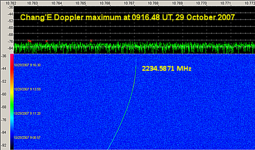
October 29, 2007 – Chang’E picked up just before
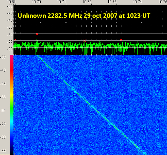
another raising of the apogee and picked up an unknown
I switched on the
tracking gear as soon as I had finished breakfast. The signal from Chang’E was
there at 0652 UT but extremely weak. It kept fading in and out but finally near
0900 UT the signal strength improved and the Doppler curve showed signs of
approaching a maximum. The maximum occurred at 0916.48 UT at the frequency
2234.5871 MHz, about 6 minutes later than the day before. The signal rapidly
faded after that at disappeared at 0917.30 UT, almost exactly as the day
before. Chinese media announced that a maneuver to a 48-hr orbit with apogee at
120000 km was planned and it was reported to have occurred at 1001 UT, 43
minutes after I lost the signal. Will I be able to pick it up when it comes
back to earth in two days?
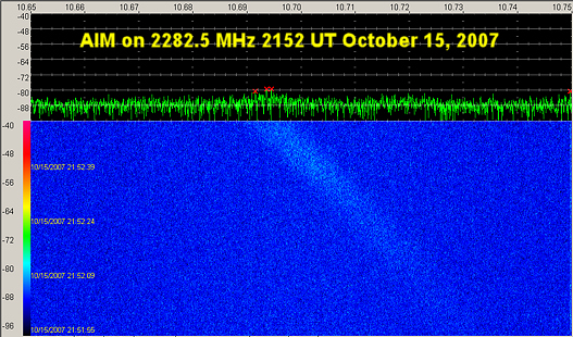
I also picked up un
unknown spacecraft on 2282.5 MHz while just waiting for AIM at 1020.30-1027.10
UT. See picture below:
Well, this is as far
as I have come up to now. The story continues. Here
are a few more spectrograms.
![]()