 Luna
16 return vehicle signals heard by Jodrell Bank in 1970
Luna
16 return vehicle signals heard by Jodrell Bank in 1970Table of contents
Luna
16 return vehicle signals heard by Jodrell Bank in 1970Below you can see a spectrogram of a part of the frequency-shift keying (FSK) pattern where the shifted period was 8.0 seconds and where the slow frequency shift is clearly seen. The 1700 Hz tone is generated by beating the incoming RF signal with a local oscillator, i.e. the tone is the difference between the received RF frequency and the frequency of the beat oscillator. When the frequency shifts, it shifts more than the audio tone frequency (here 1700 Hz) and therefore the audio tone goes through "zero beat" and then increases again. But after going through "zero beat", the RF signal has moved out of the pass-band of the IF strip of the receiver and therefore, as we can see in the figure below, is much attenuated. However, we can see that the audio tone, albeit very weak, reaches about 2300-2400 Hz, so the total frequency shift is 1700+2300=4000 Hz. (The picture below was obtained from the output of the Cool Edit software package).
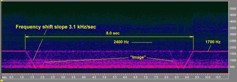
You can hear this part of the transmission (31 kB mp3).
Sometimes the interval between the frequency-shifts was 40 seconds. There were intervals with no keying and also periods with more complicated sounds.
After having done some literature research I have come to the startling conclusion that the frequency sweeps from Luna 20 are classical examples of ranging. This method was used at Cape Canaveral under the name of MISTRAM. The ground station transmits a carrier to the spacecraft and the spacecraft returns this carrier on another frequency. The ground station sweeps the uplink carrier and the phase shift of the downlink carrier is measured (counted) while it is being swept. The round-trip delay time can be shown to be T=(delta-phi)/(delta-f) ; where delta-f is the frequency shift (here ~4000 Hz) and delta-phi the measured phase shift in radians. Suppose T=2 sec (~lunar distance) then delta-phi=8000 radians, i.e. (8000*180)/Pi . Assume also that the phase can be measured with an accuracy of 1 deg, i.e. means that the range can be determined with a precision of (600000*1*Pi)/(2*8000*180)=0.33 km. In all probability there was an additional carrier quite near the one described above that remained fixed in frequency and used as a phase reference. That carrier and the two frequencies (that the sweep changed between) were probably generated as multiples of the same basic oscillator frequency. In this way all signals would have a fixed phase relationship. This is the way it was done in MISTRAM.
A Russian description of the development of this ranging system describes how it was used on all the early Luna probes as well as later Luna probes (15-24) and missions to Mars and Venus.
In (1) the wavelengths 1.6 m and 2.5 m are mentioned for the Luna series. 1.6 meters probably refers to 183.6 MHz (which is precisely 1.634 m). The wavelength 2.5 meters corresponds to 120 MHz. But, in connection with the flight of Luna 15, the Soviet Union told NASA (2) that the frequency 115 MHz was used. It is not clear of this was the up- or downlink even though (2) indicates that it is the downlink...
The rod antennas on the return craft bus were measured by enterprising persons at an aerospace exhibition where the Luna 20 return craft was displayed. The figure below shows the result of these measurements.
Let assume that the
antennas
are quarter-wave rods fed part of the way up from the "ground" end. If
that is so, then antenna AA' is resonant at the frequency fA=300/(4
* 0.36)=208 MHz. The corresponding frequency for the BB' antenna rods
is
f´B=300/(4 *
0.57)=131.6 MHz. It is probably safe to assume that the antenna system is
operating a lower frequency than calculated here. Let us assume that antenna AA'
operates at 183 MHz, then one would have to apply a correction factor to the
frequency of antenna BB' equal to the ratio (183/208)=0.88. If this is a correct
way of reasoning then the BB' antenna worked on 0.88*131.6=115.8 MHz. The
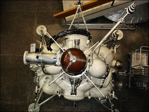
picture below I took at the kaluga Cosmonautics Museum in 2008. It shows a view
of the return vehicle and the antenna pair. The ratio between the lengths of the
antenna rods is 1.697. This would lead to an uplink frequency of 108
MHz.
However, in 2006, at the new web site of the Lavochkin association, it was revealed that the uplink frequency was 101.965 MHz and the downlink 183.537 MHz !
 |
|
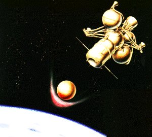
It should be noted that the landing capsule separates from the return craft bus at 50,000 km:s from the Earth and that the signals that I had were received after the separation. Did I track the bus or the re-entry vehicle? Probably the bus! However, the two pieces follow almost similar paths and tracking during the last hours of flight is probably used to pinpoint the landing spot.
from the Lavochkin web site we now know that the recovery beacons of the capsule operated on 121.5 MHz (the international distress frequency) and 114.167 MHz.