 Short-wave
radio systemsShort-wave
radio systems
Short-wave
radio systemsShort-wave
radio systems18.060 MHz AM voice has also been reported from Soyuz-9 and Soyuz-18 (when docked to Salyut 4). The onboard transmitter power on short waves was 3 Watts. Simplex voice was probably the most common but as we know from the observations of Chris van den Berg duplex was also possible with reception of AM voice from the ground on 22.205 MHz.
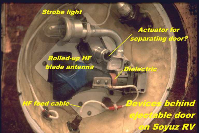
HF is still used on late model Soyuz spacecraft during the recovery phase, when Morse code (the Morse-code characters AN) and AM voice can be transmitted on 18.060 MHz. Morse code beacon (AN) only is transmitted on 8.364 MHz during recovery operations. The antenna is a whip antenna that is stored as a rolled-up steel band under a little door in the upper part of the re-entry vehicle (See picture).
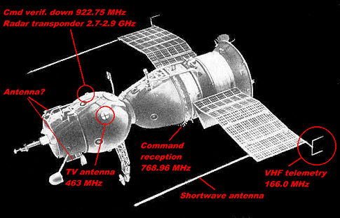
The VHF voice communications system probably operated both in simplex and duplex mode. In the duplex mode 130.167 MHz is the uplink and 121.75 MHz is the downlink. In the simplex mode 121.75 MHz is used in both directions. However, in Mir flights 130.167 MHz has been used for downlink and it is feasible that even early Soyuz craft could use this as an alternate downlink in the duplex mode (with 121.75 MHz as uplink). It is difficult to locate the antennas for the VHF voice on early models of Soyuz. The devices marked Antenna? in the figure above could possibly be such antennas.
For ASTP and Soyuz 22 the frequency 142.417 MHz was used for downlink FM voice so that 121.75 MHz could be used for inter-ship communications with Apollo-18.
 VHF
Telemetry system
VHF
Telemetry systemThis system has been replaced by the PCM-FM system called BR-9TsU-3 also operating on 166.0 MHz. The transmitter power is about 7 Watts. Soyuz 16, 19, and 22, the ASTP models of Soyuz also transmitted PCM-FM telemetry but, on 192.0 MHz. The data rate in the PCM version is 256 kbps.
Early Soyuz version had U-shaped
antennas at the tip of the solar panels. The eariest model, 7K-OK, had
the U-shaped antennas at the "rear" tip of the solar panels. The ASTP vehicles
(Soyuz 16, 19 and 22), 7K-TM, had these antennas at the midpoint of the
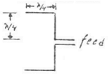
outer edge of the solar panels. In (1) the
omnidirectional charcteristics of such an antenna is described. A simple
sketch of the principle of the antenna is hown on the right.
 UHF
Television system
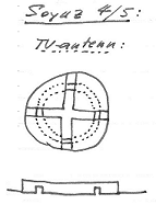
UHF
Television systemThe antenna is a "crossed slot" design shown on the right. This sketch was made by myself after examining the Soyuz-4/5 full scale mock-ups displayed at the Soviet Space Exhibition in Stockholm in 1978.
Commands are downlinked to provide a verification of receipt. The frequency of this downlink is922.75 MHz. The antenna system for this frequency consists of two half-wave loops (See picture) mounted 180 degrees apart on a band that circles the orbital module. Just behind the dipoles there is a disk, which is believed to contain the 2.7-2.9 GHz radar transponder antenna.
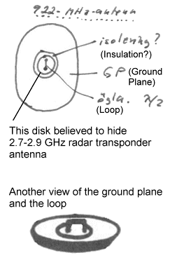 The
details of this antenna "ensemble" is shown in the figure on the right
(see also picture), which
is based on a sketch that I made after examining the Soyuz-4/5 full scale
mock-ups displayed at the Soviet Space Exhibition in Stockholm in 1978.
The
details of this antenna "ensemble" is shown in the figure on the right
(see also picture), which
is based on a sketch that I made after examining the Soyuz-4/5 full scale
mock-ups displayed at the Soviet Space Exhibition in Stockholm in 1978.
Both low rate command-copy signals and wide band telemetry signals have been observed on the downlink. It is also probable that Klest TV signals can be routed through this transmitter. The transmitter power is probably about 10 Watts.
![]()