 |
 |
 |
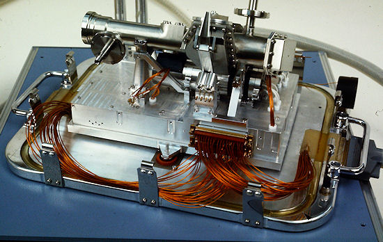
Above left: The
whole experiment mounted on the bottom plate of its transport
box.
|
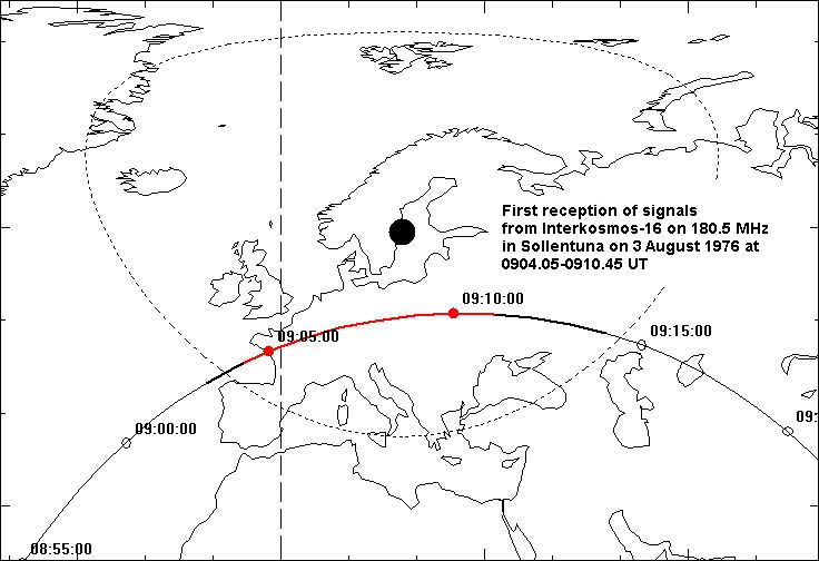
Sven Grahn
A Swedish satellite-borne optical experiment for the study
of ultraviolet light from processes on the sun was proposed by the young
scientist Jan-Olof Stenflo (1)
at the Institute of Astronomy of
the University of Lund (AIL) in Southern Sweden. Stenflo's Ph.D. thesis in 1968 treated
the Sun's magnetic field and was based on observations made in the
mid-60's from the Astrophysical Observatory in the Crimea. Together with his colleagues
in the Crimea he succeeded in convincing Swedish and Soviet
space agencies to build this experiment and launch it on a Soviet
satellite.
The newly-started government-owned Swedish Space
Corporation (SSC) got the task to manage the project on behalf of the
Swedish Board for Space Activities (nowadays the Swedish National Space Board).
The optical parts were built by Jungner Instruments (7)
and the encoder electronics by Saab-Scania. SSC
built the detector electronics, the sunsensors and carried
out the final test of the system in its laboratories at Tritonvägen 27
in Solna, a subsurb of Stockholm.
Above left: The
whole experiment mounted on the bottom plate of its transport
box.
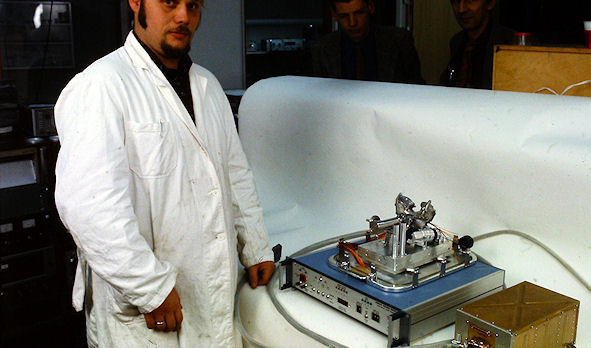
Above right:
Lars Stenmark (SSC) with the spectrometer, encoder and support
equipment.
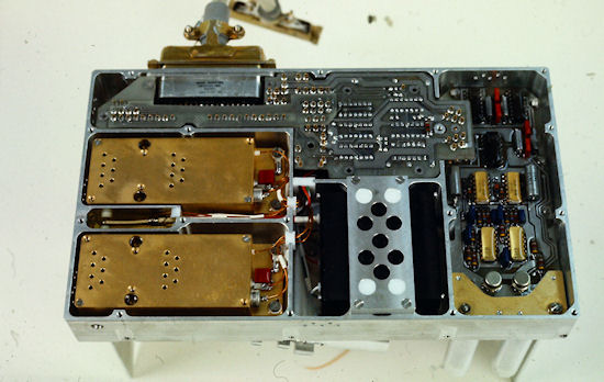
Left: The experimentet from below.
 The primary scientific aim of the experiment was to
investigate the solar
transition zone between the chromosphere and the
corona (5) .
The registered wavelength region
was within the spectral interval
1200 - 1500 Å. The instrument measured the
polarization of the sunlight which was used as a diagnostic of the temperature
gradient in the transition zone and of the magnetic
field.
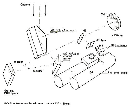
The experiment was designed to record
linear polarization in two fixed directions, parallel and perpendicular to the
dispersion direction. The main techniques of analyzing linear polarization in
the VUV made use of the fact that obliquely reflected light is partially
polarized. If the reflection occurs at a dielectric surface at the Brewster angle
, the reflected light is 100% linearly polarized,
but the reflectivity is low. Certain coatings, like gold, give about
70% polarization at an angle of incidence around 60°, combined with high
reflectivity. In Stenflo's experiment the polarization analysis took place already at
the first two optical components, two plane mirrors divided in two halves with
different coatings, gold and Al+MgF2, respectively. The latter
coating gives less than about 5% polarization. The two beams reflected at the
two different coatings were focused through the same exit slit and were then
geometrically separated to feed two separate photomultipliers.
The primary scientific aim of the experiment was to
investigate the solar
transition zone between the chromosphere and the
corona (5) .
The registered wavelength region
was within the spectral interval
1200 - 1500 Å. The instrument measured the
polarization of the sunlight which was used as a diagnostic of the temperature
gradient in the transition zone and of the magnetic
field.
The experiment was designed to record
linear polarization in two fixed directions, parallel and perpendicular to the
dispersion direction. The main techniques of analyzing linear polarization in
the VUV made use of the fact that obliquely reflected light is partially
polarized. If the reflection occurs at a dielectric surface at the Brewster angle
, the reflected light is 100% linearly polarized,
but the reflectivity is low. Certain coatings, like gold, give about
70% polarization at an angle of incidence around 60°, combined with high
reflectivity. In Stenflo's experiment the polarization analysis took place already at
the first two optical components, two plane mirrors divided in two halves with
different coatings, gold and Al+MgF2, respectively. The latter
coating gives less than about 5% polarization. The two beams reflected at the
two different coatings were focused through the same exit slit and were then
geometrically separated to feed two separate photomultipliers.
These two
parallel optical channels responded quite differently to light polarized parallel
and perpendicular to the dispersion direction, so the ratio between the count
rates of the two channels contained information on the amount of linear
polarization of the incoming light. The polarization characteristics of the
instruent were calibrated at a UV test facility at the Max-Planck Institut für Extraterrestrische Physik in Garching
outside Munich.
A plane objective grating
produced a slitless solar spectrum, with solar images in each emission line
superposed on a background smeared-out continuous spectrum. There were no moving parts in the instrument. The
slitless spectrum was scanned by a tilting motion of the whole satellite, which
was performed on command from a ground station. The effective spatial resolution
in one dimension was about 0.5 arc-minute.
The
photomultipliers with type number PM
426 L had a sideways-looking MgF2 window and were
manufactured by the French company R.T.C. (La Radiotechnique-
In addition to the photomultiplier signals two sun sensor signals (X- and Y-directions) were tranmistted to the ground (2). The sketch above shows the optical configuration. The entire experiment weighed about 6 kg (4) . The optics box, which was mounted on the outside of the pressurized body of the satellite, measured 250 x 150 x 180 mm. The encoder, measuring 280 x 158 x 125 mm, was placed inside the the part of the satellite that was pressurized by N2 to 0.87 atm.
To transmit data to
the ground the satellite used four synchronous commutators to which the four
outputs from the Swedish encoder were connected. Each measurement value was
reconstituted by combining the output from the four commutators. The analog
values in the commutator are discretized into 12 levels, the lowest and highest
of which are used for synchronization, the other 10 for data. So, the data from
the spectrometer was converted by the Swedish encoder into four analog channels
each with a voltage in one of 10 levels (1.200-4.800 Volt in 0.400 V steps) and
that voltage then represented a decimal value. Level 0 was the decimal digit 0.
Level 9 was the decimal digit 9 etc. So, by combining the four digits
from the four commutators it was possible to transmit values in the range
0-9999. The encoder also sent a square wave in synchronization with the word
rate to a fifth commutator.
On the ground the analog output values from the telemetry system were sampled with 8-bit resolution and this binary-coded representation of the voltage levels were recorded on raw data tapes that were sent to the Swedish side. The tape recorder used at the data center in Moscow was loaned to the Soviet side by the Swedish side.
Details of the operation of the experiment in orbit are given in (3) och(5) . As already mentioned t
he scanning of the spectrum was carried out through controlled scans of the satellite axis along the diagonal of a square having dimensions between +/- 70 arcminutes and +/- 160 arcminutes. During the controlled scan, the angular velocity components parallell to the sides of the square were in the interval 100-250 arcseconds /sec. The roll rate was limited to less than 0.05 deg/sec.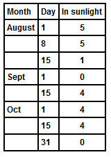
 The
The
The launch time of the day was chosen with this in mind, obviously. To be able to collect science data the satellite had to be in sunlight when passing the ground station. Let us use the ground station at Yevpatoria as an example. The orbital plane rotated in relation to the inertial coordinate system and therefore also in relation to the sun. This would cause periods when the passes over the Soviet Union would occur in darkness. The table above left shows the number of passes over Yevpatoria in sunlight. Of course other stations could have supported the mission, but nevertheless there were some periods when no data could be collected.
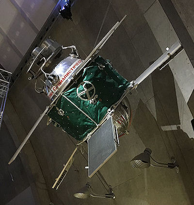
Interkosmos-16 was based on the standardized small satellite design in the DS-series (DS= 'DnepropetrovskSputnik') developed by Mikhail Yangel's design bureau OKB-586 (a.k.a. KB Yuzhnoye) in the Ukraine. These satellites were launched by rockets from the same organization. The satellites were used for a wide range of military and civilian purposes. The text here is based on (6) .
The preliminary design of the more advanced DS-U family of satellites was completed in 1963. Yangel proposed a standardized series of satellites with the following characteristics:
Interkosmos-16 was a DS-U3 vehicle with the suffix "IK" for Interkosmos. Six such satellites were built. The picture above shows a full-scale replica of a DS-U3 satellite on display at the Science Museum in Stockholm.
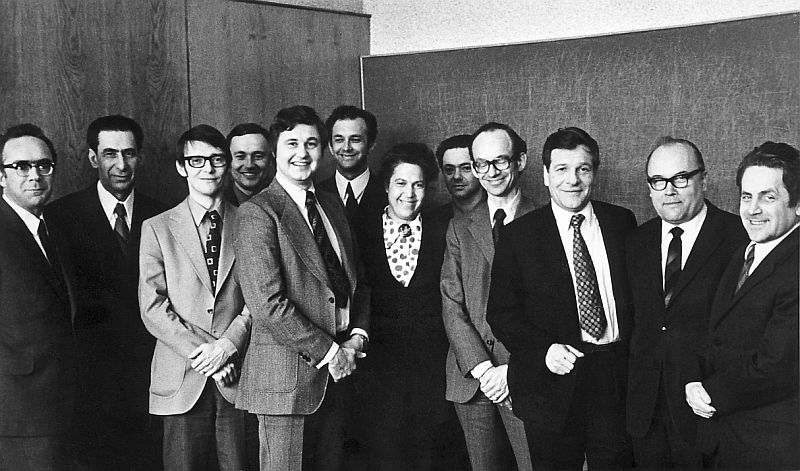
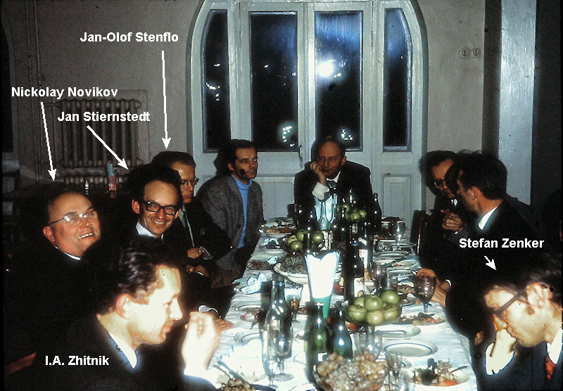
Negotiations with the Soviet sideThe black-and-white picture below was taken in December 1972 and shows participants in a meeting in Moscow about the project. The Space Research Institute (IKI) in Moscow was represented as well as the research institute IZMIRAN outside Moscow. Left to right: Unknown, Yan L. Ziman (IKI), Stefan Zenker (project manager for the experiment at SSC), unknown, Fredrik Engström (CEO of SSC), Yuri Preobrazhenskiy (IKI), Unknown (interpreter?), Yuri I. Galperin (IKI), Jan Stiernstedt (chairman of the Swedish Board for Space Activities), Valeriy Zolotukhin (deputy head of IKI), Nikolay Novikov (Vice-president of the Intercosmos Council), Igor S. Zhulin (IZMIRAN). The picture has been provided by Mr Stefan Zenker who found it in his archive by pure chance in early 2016. It had probably been sent to him by Andrey Bruns at the Crimean Astrophysical Observatory.
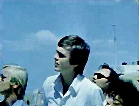
The colour picture below it was taken
by SSC engineer Lars Anderson in December 1972 when the Swedish side of the
project visited Moscow and the Crimea.
 |
 |
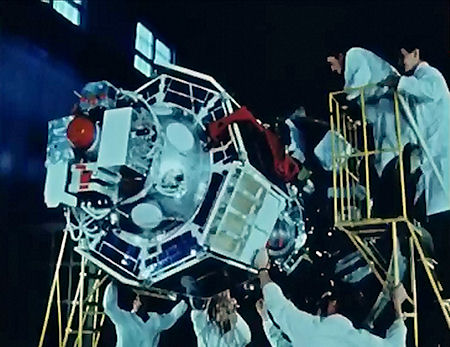
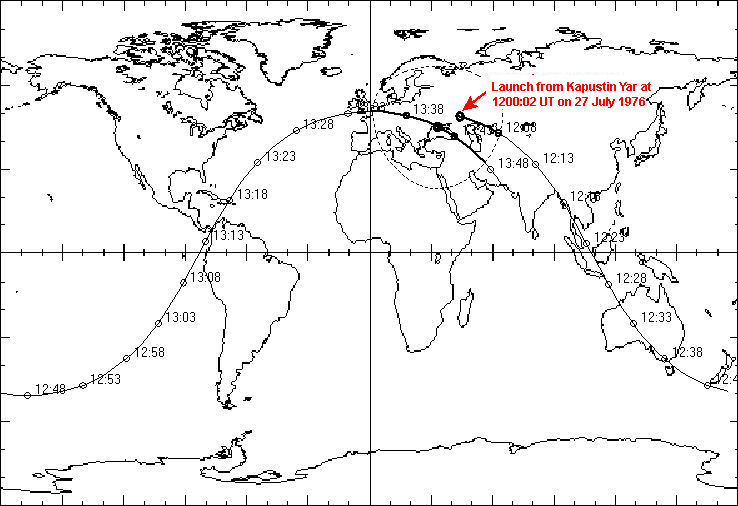
A spare copy of the experiment was prepared and at 1200:02 UT on 27
July 1976 the
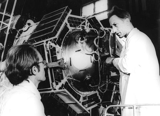
This time Jan-Olof Stenflo (AIL) and
two engineers from SSC (Anders Björkman and Pierre Lingheim) were present at
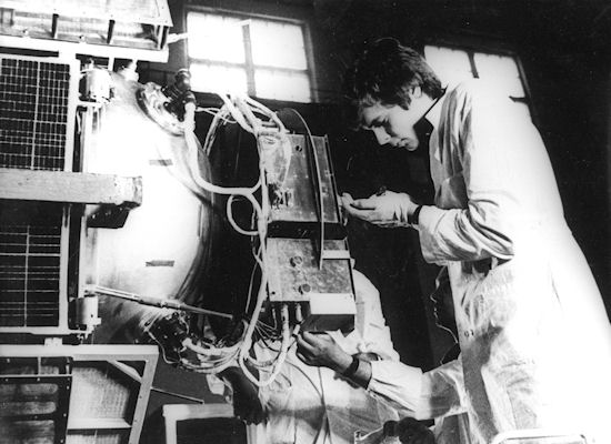
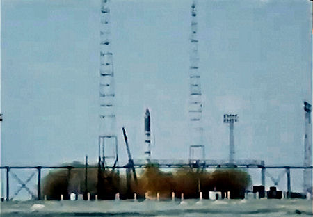
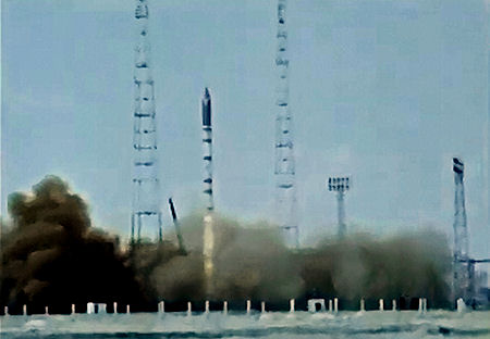
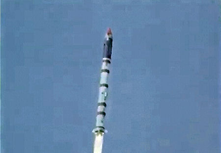
the launch site. Below are the offical Soviet still pictures from preparations
at the launch site.
 |
 |
 |
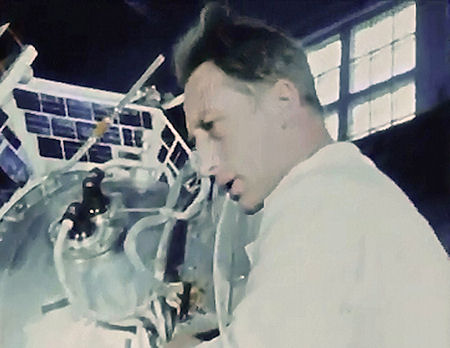
Above left.: Pierre Lingheim (SSC) working on the
experiment on the satellite.
|
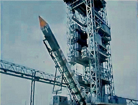
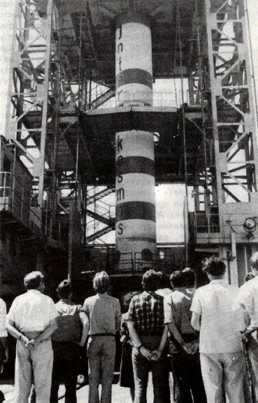
I
found the picture below many years
ago in the Dutch magazine Spaceview. It shows the Kosmos-3M-rocket in the
service tower. Jan-Olof Stenflo is the third from the
left.
 |
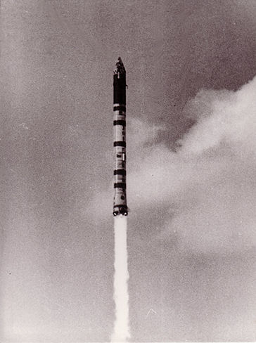
Official Soviet launch photo
 |
This is the first orbit around the
Earth. The satellite passed straight over a ground station in the
Crimea (Yevpatoria).
 |
The pictures below come from this clip.
|
|
|
|
|
|
|
|
 |
 |
 |
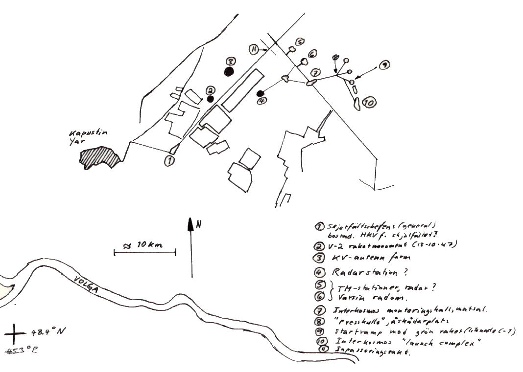
When my colleagues att SSC, Björkman and Lingheim, returned from the Soviet
Union I interviewed them about their impressions of Kapustin Yar. We
looked at a rather bad Landsat picture of Kapustin Yar and they drew this
sketch from that picture: 1.Range commander's residence, 2. V-2 monument (in
memory of first launch 13 october 1947), 3. Shortwave antenna "farm", 4. Radar station
(?), 5. and 6. Radar or telemetry stations
in radomes, 7. Assembly hall for the Interkosmos-16 launch vehicle plus dining hall,
8. Launch viewing area, 9. Launch pad with "green" rocket, 10. Interkosmos launch
complex, 11. Entry guard house.
 |
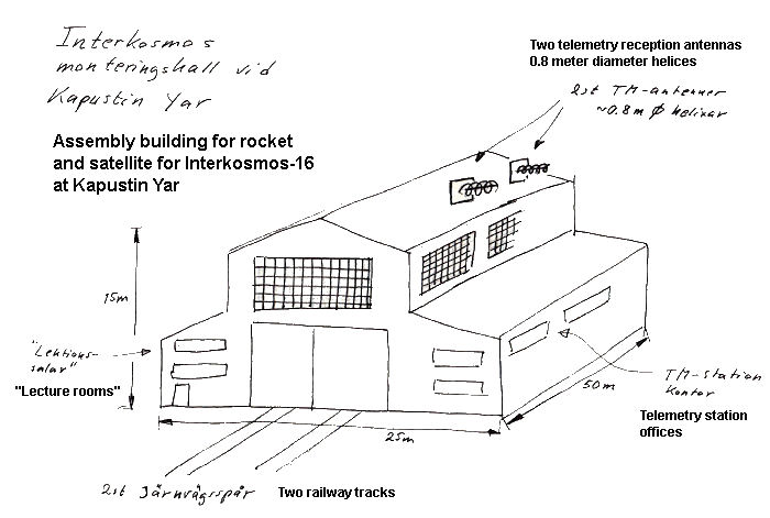
Based on what they told
me I also drew this sketch of the assembly
hall.
 |