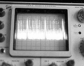
 Free-running time-base. Word-definition "marker" pulses clearly visible, word-value pulses form "fog" |
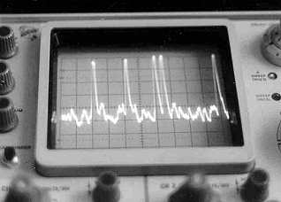 Single-sweep. Two words visible, the left one at 50% of distance between markers, the right one at 10%. |
Sven Grahn
This type of telemetry was used by many types of automated and piloted spacecraft launched by the Soviet Union. The description below is based on my own observations of this signal. In all probability my observations only cover a subset of this basic telemetry system which probably is the RTS-9 system.
PPM-AM signals on 166.0 MHz were received on August 16, 1981 from Kosmos 1286 (81-72A) an EORSAT (Elint Ocean Reconnaissance satellite), Russian designation US-P, launched from Baikonur on August 4, 1981 into a 432-445 km orbit inclined at 65o. The receiver used was a Nems-Clark 1302A telemetry receiver which has an intermediate-frequency bandwidth of 300 kHz and a video bandwidth (output) of 300 kHz. The output was fed to a normal Tektronix oscilloscope to produce the pictures below.
Free-running time-base. Word-definition "marker" pulses clearly visible, word-value pulses form "fog" |
Single-sweep. Two words visible, the left one at 50% of distance between markers, the right one at 10%. |
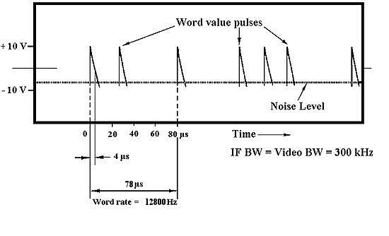
In this pulsed AM transmission 4 microsecond long pulses are transmitted every 78 microseconds. These "marker" pulses define words in the telemetry format. Within each such interval a word value pulse is transmitted. Its position in the 78 microsecond word interval defines the particluar word value transmitted. Therefore the telemetry system is called pulse-position modulated amplitude modulation (PPM-AM). There is also a second mode of the telemetry system with word interval length equal to 96 microseconds. The figure below illustrates the pinciple. It shows a simplified sketch of of the oscilloscope output from the Nems-Clarke 1302A telemetry receiver.
In (1 ) we can find a detailed description of the telemetry system RTS-9 which was used on i.a. early Soyuz models and obviously also on Kosmos-1286. The basic telemetry channel definition can be seen in the figure below.
Tr = the repetition period of reference pulses. In the general case the repetition frequency of reference pulses in the RTS-9 PPM system could be 25.6 kHz, 12.8 kHz, 6.4 kHz, 3.2 kHz (Tr = 39.0625 µsec, 78.125 µsec , 117.1875 µsec , 234.375 µsec ).
The simplest RTS-9 PPM system used a single 32-channel commutator. The next level of complexity useda main commutator with 8 steps (timeslots), the last of which contained no measurement pulse and had the role of a synchronisation signal. Each time the main commutator cycled through the 8 steps each subcommutator moved ahead one step. There was also a 64-chennel subcommutator. So, there were three RTS-9 PPM systems: 32 channels, 8x32=256 channels, and 8x64=512 channels. It seems that there was a version in which the subcommutator positions were not synchronized with each other and another variant in which they were. The frame sync of the subcommutator were sent as three pulses in the protection intervals of the three last channels of frame, which did not contain measuring pulses. So, the following channels were used for this: 30, 31 and 32 (in the 32-channel system) or 62 and 63 and 64 (in the 64-channel system). The 10% position pulse in the rightmost oscilloscope picture above probably shows such a synchronization pulse.
One of the first telemetry systems that Soviet engineers put together used a main commutator having 12 segments (or channels) and no sub-commutators. Simpler because no sub-commutators had to be synchronized. When more instrument data was required, their new 12 segment commutators were used as sub-commutators for a four segment main commutator, all being done mechanically. This yielded 48 channels, each with a duration of about 166.6 microseconds, and a complete frame of all 48 channels in 8000 microseconds, for a frame rate of 125 per second. As the main commutator slowly progressed from segment to segment, all 12 of the sub-commutator inputs were sampled. This became the mainstay system, but many other forms were used, suppressing channels, adding channels, eliminating or adding main commutator segments, and so on. This the system known as Tral ("Trawl").
So, Tral was an early telemetry system used i.a. in the R-7 missile and Sputnik-3. It was a PPM system. The PPM timeslot is divided into a protection, measuring and signal interval as follows (1 ):
The timeslot length - T0 - was 166.6 µsec.
 48 timeslots in succession is called
the telemetry frame of "Tral". The composition of the frame includes both the
measuring and auxiliary information.
48 timeslots in succession is called
the telemetry frame of "Tral". The composition of the frame includes both the
measuring and auxiliary information.
The 4x12 commutation scheme is described like this in (1 ): The beginning of each frame is defined by the marker M1, which consists of 4 pulses. The marker is designed to synchronize the transmitting and receiving equipment. He passed before a new measurement cycle in the 48th channel of the previous frame. Marker M1 is also called the M125. It is easy to calculate that, with a duration of 8 ms frame repetition rate of the measurement cycle is 125 Hz. Each measurement cycle (frame) is divided into four equal groups of markers M2, M3, M4, which are called markers of the group. These markers represent a code group, consisting of 3 pulses. M2, M3 and M4 are transmitted in channels 12,24 and 36,i.e. every 2 ms so the repetition rate of the markers is 500Hz. The entire marker group is also called the M500. The marker groups are transmitted in the signalling interval.
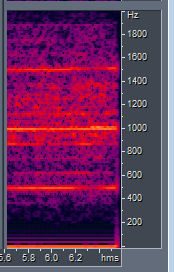
It is interesting that by just tuning a narrowband AM receiver to the Tral spectrum one can hear the M500 markers and their overtones. The M125 markers are also visible in the spectrum on the right. This recording of signals on 66.2 MHz from Kosmos-353 was made on July 12, 1970 - see section "My own Tral tracking.. ." below.
The initial Tral system probably operated on the frequencies 61, 66, 71, and 76 MHz. I only received it on approximately 66.0 MHz, 66.2 MHz and 66.45 MHz from Kosmos reconnaisannce satellites of some particular types (Zenit-2M, Gektor) and also once from the last stage of the Molniya launcher when it was used to launch a Venus probe. So, it seems that there was some sort of additional channelization of the basic five slots in the 61-76 MHz range. I think the figure below shows how it worked. Now, of course we also know other frequencies were used for Tral .
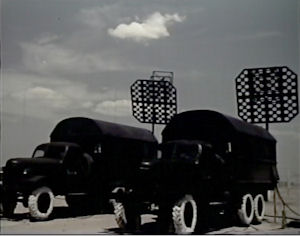
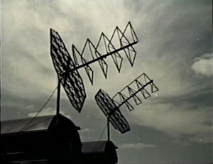
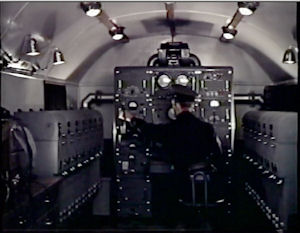
In the Soviet documentary (Film number 112) about the R-7 missile, we can find pictures of Tral telemetry vans and reception antennas.
 |
 |
 |
In the book "Soviet Space Technology" (2) by Alfred Zaehringer I found that Sputnik-7, an unsuccessful Venus probe, used the frequencies 66 and 66.2 MHz and that the signals on these frequencies did not come from the Venus probe itself but rather from the satellite from which the Venus probe was injected into the trajectory to Venus. Sputnik-7 was launched on 4 February 1961 but the Venus probe never left Earth orbit. Eight days later an identical satellite, Sputnik-8, was launched and succeeded in sending Venera-1 in the direction of Venus.
I decided to try to determine how 66 MHz and adjacent frequencies were used by Soviet satellites and therefore ordered a frequency converter from the U.S. company Vanguard Electronic Labs which made converters to the customers specification. But a complication was that this frequency range was used for television (TV-channel 4) in many parts of Sweden including Stockholm. The same was true in all Western European countries. Fortunately my parents had a cottage near the city of Gävle north of Stockholm where channel 4 was not in use the frequency range was completely empty. I put up a TV antenna for channel 4 and pointed it to the southeast.
During the summer of 1970 I was doing compulsory military service in the city of Uppsala between Stockholm and Gävle and went to my parents summer cottage over weekends. To have something interesting to do I brought my radios there and listened to such signals as the usual signals on 19.995 MHz from Kosmos photoreconnaissance satellites. Kosmos-353 was a photoreconnaissance satellite of a type that remained in space for twelve days and transmitted FSK-PDM signals on 19.995 MHz. When I heard it on the shortwave radio in my parents cottage I quickly turned on the frequency converter for 66 MHz and heard a very strong buzzing sound on 66.2 MHz. I listened on several orbits passing Sweden and the signal came back every time. The VHF transmitter always started exactly 21 seconds after the start of signals on shortwaves. During the summer and autumn of 1970 I heard several '12-day satellites' on 66.2 MHz.
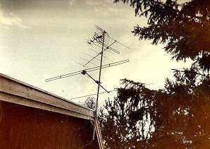
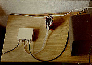
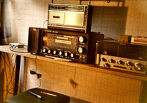
The picture on the left shows the TV antenna for channel 4 that I used to pick up 66 MHz signals at the bottom of the TV-antenne mast of my parents' house. The middle picture shows the converter that changed the frequency range 66-71 MHz to 7-11 MHz. The incoming and outgoing coax cables can be seen as well as the battery pack that drove the converter. The picture on the right shows the converter, the Lafayette HE-30 receiver used to tune the 7-11 MHz range and on top of it the tape recorder.
I used this set-up also to receive signals from the failed Venus probe Kosmos-359.
 |
 |
 |