Official descriptions of the radio systems
Venera 1:
When Venera-1 was launched in February 1961 Soviet news
media announced that the probe transmitted on 922.8 MHz. The tradition of
publshing transmission frequencies started with early space launches contined.
The idea was probably that foreign radio observatories could pick up the
transmissions and thereby verifying any possible claims of Soviet authorities
as to the final fate of the spacecraft
Mars-1:
For Mars-1,
launched in November 1962, Soviet news media provided the following
brief description of the probe's radio systems:
"The craft carries three radio systems, working on wavelengths in the metre (1.6m), decimetre (32cm) and centimetre (5 and 8 cm) ranges....The radio complex working in the metre range serves both for transmission of telemetric information about condition of the station and for maintaining communication with the earth in the event of abnormal functioning of the orientation system." (1)
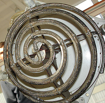
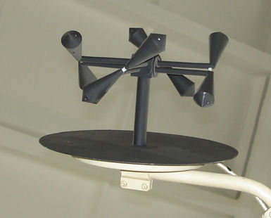
No precise numbers were given this time, but the numbers provided still gave a clue to the actual frequencies. We now know that this text should be interpreted so that the main radio link from Mars-1 to earth operated on 922.76 MHz ("decimeter" or "32 cm band"). We also know that the corresponding uplink from earth worked on 768.96 MHz (refrred to in Soviet literature as the 39.cm band). The "metre-band" back-up link worked on 183.6 MHz down and the uplink was probably near 102 MHz as it was for early lunar probes. It appears that the metre band was only used for the 2MV spacecraft. For radio science measurements near Mars a signal coherent with the main 922.76 MHz link was transmitted on four times that frequency, i.e. on 3691.04 MHz - the "8 cm band". In addition there was an additional link in the "5 cm-band" which we now know meant the 5840-5890 MHz range. The omni antenna for 32 cm is probably of the design shown in Picture 4 (this picture was taken by myself in the Energia museum in Moscow).
Zond-1,
Venera-5,6,7,8
Soviet media gave the transmission frequency
of Zond-1 as 922.76 MHz and of Venera-5 and 6 as 922.763 MHz. The transmission
frequencies of Venera-7 and 8 were given as 928.429 MHz.
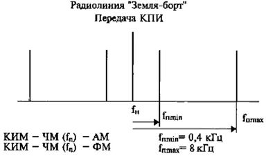
The metre band
link
Very little is known from Western
sources about the modulation scheme of the metre band transmissions from
interplanetary probes. Metre band radio systems were most probbaly used only by
the 2MV series of space probes. According to(6) PCM-FM-AM was used on the uplink and PCM-PM was used on the
downlink. The rightmost modulation method denotes
the modulation of the main carrier.
The 32-cm (decimeter) downlink
 For Mars-1 Moscow sent a message to Jodrell Bank (2)
giving details about the
modulation used on one of the radio systems of Mars 1:
For Mars-1 Moscow sent a message to Jodrell Bank (2)
giving details about the
modulation used on one of the radio systems of Mars 1:
"The telemetry transmitter operates on 922.8 MHz with +/- 120 deg phase modulation with the subcarrier frequency in the range 1100-1700 Hz, during telemetry transmission the subcarrier frequency is modulated in frequency by a code signal."
For the M-69 Mars project the 32/39 cm link was designed to receive radio commands, to measure the radial distance and velocity, and to transfer the telemetry data. The onboard transponder operated at 100 watts of power, and data were transmitted at a rate of 128 bits/sec The telemetry system, designed with 500 channels to provide the data from the onboard systems.(3). In (7) details are given in graphical form about the data rate and signal spectra for this telemetry system showing how subcarriers were modulated by the pulse-code-modulated data stream and then phase-modulated on the main carrier.
For Venera-4 (4) indicates that the decimeter radio system transmitted telemetry data to Earth at speeds 1, 4, 16 and 64 bits per second. Power of the decimeter transmitter - was 40 watts.
In (11) Don Mitchell writes: "...at some point, probably beginning with Venera-9, the modulation scheme was changed from frequency shift keying to phase shift keying . In this system, binary zero and one are represented by 180° differences in phase. PSK is more energy efficient than FSK,"
The 39-cm (decimeter) uplink
For Venera-4 (4) indicates that the decimeter radio system could receive up to 127 discrete commands from Earth. In later versions of the comand system not only simple functional, discrete, commands could be sent, but also numerical data (digital data such a software) (6) .
The 8-cm link
According to (11) a 20-watt, 200 pixel/sec PPM image telemetry system was designed for the Zond-2 Mars mission. Alternatively, it could transmit images on 8-centimeters with frequency shift keying, at 512, 1024, 2048 or 4096 bits/sec.
The 5 cm link
Impulse modulation
The modulation is described in
(3)
as "impulse modulation".
For
Mars-1 the image data would be tranmitted at approximately 90 pixels/sec, using
pulse-position modulation in 25 kilowatt spikes. The average power
consumption was 50 watts (10).
For the M-69 project the impulse transmitter was designed to transmit images of the Martian surface to Earth. It operated at a power of 25 kilowatts (per pulse), and data were transmitted at a rate of 6,000 bits/sec (3) . It appears from (6) that Pulse-Position-Modulated (called Pulse-Time-Modulation in Russian terminology) were transmitted on 5844 MHz. By examining the signal spectrum shown in (7) one can draw the conclusion that the pulse width was about 0.83 µs.
According to (11) the Mars missions, M-69 (which was destroyed at launch) and Mars-2 to Mars-7 used several telemetry systems, including 1024 pixels/sec (about 6144 bits/sec) image transmission with PPM on the 5-centimeter band and science data at 128 bits/sec with continuous-wave FSK. Venera-9 returned the first images of the surface of Venus, using a digital FM system at 256 bits/sec on each of two camera channels. After the 1973 Mars missions, the use of pulse position modulation was discontinued.
Phase modulation
The frequency given here for the 5-cm link
(5.87-5.89 GHz, center frequency 5.88 GHz) comes from (5) .
In
(6) data are give for the Fobos missions.
The phase modulation of the encoded 16 384 bps data is ± 1.3 rad, transmitter
power 50 watts at 5885 MHz. The corresponding uplink is given as
5008 MHz. The Fobos missions were the first utilizing this
combination of up and downlink.
Venera-15: A radio link at 5 cm wavelength provided a data transmission rate of 100 kbits/sec from the spacecraft to Earth at all distance up to the maximum of 260 million Km.
Early landers - a
direct-to-earth link
On the early landers (Venera-2 to -8) scientific
data from the landers were transmitted directly to earth on the 32-cm band link.
A relay through the main spacecrfat was difficut to arrange because the main
spacecraft could have burned up in the planet's atmosphere or crashed on its
surface by the time the landing capsule touched down. It also seems that
the same frequency as that of the main spacecraft was used also for the landers.
The reason for this assumption is that Jodrell bank picked up signals from the
descent vehicle of Venera-4 on the same frequency as the main spacecraft. The
antenna on the lander needed to have low gain in order to ensure that the link
to earth was not blocked. This, and the very long distance to earth, led to very
low data rates (1 bit/sec) from the descent and landing on Venus. Cleraly such a
low transission rate would not be sufficient to transmit any pictures from the
surfec during h evry short lifetine of the lander (approximately an hour) on the
surface of Venus. The use of the 32-cm band for the lander-earth link is logical
because the antenna size on earth is fixed and the antenna gain on the lander is
fixed. In such a case the basic link budget is independent of frequency.
Later landers - relay through
the main spacecraft
For the
4V and M-71 landers and following spacecraft models the signals
from the landers would be relayed through the main spacecraft, either
during a flyby or while in orbit around the planet. The frequency of
this intersatellite link needed to be as low as possible. It can easily be shown that
when communicationg between two antenna with fixed gains (determied by providing
sufficient coverage) the frequency should be chosen to be as low as
practically possible (the size of the antennas may be limted by geometrical
concerns) (9). In (6) the frequencies used by lander
to main spacecraft link are given as122.8 MHz and 138.6 MHz. It appears that
each of the two frequencies carried data from a different
camera.
Venus:
According to (11) there was a 512 bit/sec connection
from the Venera lander and a 3072 bit/sec connection to earth, the orbiter
relayed data in real time and also recorded it on tape for several later
playbacks. In (6)
the data rate is given as
3072 bits/sec transmtted on a subcarrier at 30,72 kHz.
In (10)
the data rate to earth is given as 3072
bits/sec.
Mars:According to (3) data from Mars landers would be
transmitted to the Martian satellite at a speed of 72,000 bits/sec in two
independent radio channels. The circular panoramic images of the landing site
would be transmitted as an image of 500 x 6,000 pixels. Each minute the video
information would have to be interrupted by the telemetry data. The period
calculated for each communication session would be 18-23 minutes. After the
first communication session, the onboard transmitters would be disconnected and
the station transferred to a survival state. The second communication session
would be initiated by a transmitted signal. Its period would depend on the
position of the landing site and could be 0.7-5 minutes.
Also according to (11) the cameras scanned back and forth, sweeping out a 115 × 512 pixel panorama, which was digitized to 6 bits per pixel, with a 7th parity bit. A small images size (compared to Luna-9's 500 × 6000) was motivated by telemetry rates and an estimated 30-minute minimum lifetime. Two meter-band channels carried 256 bits/sec each, a conservative rate dictated by a low target error rate and the semi-directional transmitting antenna.
The Fobos spacecraft was intended to land an autonomous station of the Marian moon. It would communicate with Earth on 1672 MHz. The PROP-F "hoppers" may have used 280 MHz return link and 401.5 MHz forward link - I think.
The Mars-96 spacecraft carried "penetrators" that used the international standard 401.529/437.1 MHz link.
The table below summarizes my knowledge of frequencies used by Soviet/Russian interplanetary probes. Numbers maked red come directly from Soviet media reports an later post-Soviet literature. Data from Joe Bruman at JPL marked blue. Numbers marked green come from the Library of Congress reports on the Soviet space program.
| Spacecraft | Purpose | Flight |
Metre
band |
32/39
cm MHz |
8
cm MHz |
5
cm GHz |
X-band GHz |
Lander-probe | Lander-earth |
| Venera |
- |
||||||||
| 1VA | Venus impact | Venera-1 |
- |
922.8 /769 |
- |
- |
- |
- |
- |
| 2MV-1 | Venus landing | 25 Aug/1 sept 62 failures | 183.6/101.9 | 922.76/768.96 | 3691.04 | 5.84? |
- |
- |
922.76 |
| 2MV-2 | Venus photo flyby | Sept 12, 1962 failure | 183.6/101.9 | 922.76/768.96 | 3691.04 | 5.84 |
- |
- |
- |
| 3MV-1A | Venus test flight | Kosmos-21, Feb 19, 1964 |
- |
- |
- |
922 | |||
| 3MV-1 | Venus landing | K-27, Zond-1 |
- |
922.76 /768.96 |
- |
- |
922.76 | ||
| 3MV-2 | Venus photo flyby | Venera-2 |
- |
922.763 /768.969 |
- |
- |
- | ||
| 3MV-3 | Venus landing | Venera-3 |
- |
922.763 /768.969 |
- |
- |
922.76 | ||
| 1V | Venus landing | Venera-4 |
- |
928.4/773.7 |
- |
- |
928.4 | ||
| 2V | Venus landing | Venera-5,6 |
- |
922.763 /768.969 |
- |
- |
922.763 | ||
| 3V | Venus landing | Venera-7,8 |
- |
928.429 /773.691 | 5.895 |
- |
- |
928.429 | |
| 4V-1 | Venus landing | Venera-9,10 |
- |
922.763/768.969 | 3691.04 |
- |
122.8 & 138.6 |
- | |
| 4V-1 | Venus landing | Venera-11,12 |
- |
928.4/ 773.7 | 3713.6 | 5.859 |
- |
122.8 & 138.6 |
- |
| 4V-1M | Venus landing | Venera-13,14 |
- |
928.4/773.7? |
- |
122.8 & 138.6 |
- | ||
| 4V-2 | Venus orbit | Venera-15,16 |
- |
928.4/773.7? |
- |
- |
- | ||
| 5VK | Venus landing | Vega-1.2 |
- |
928.4/773.7? |
- |
122.8 & 138.6 |
- | ||
| Mars |
- |
||||||||
| 1M | Mars flyby | Oct 1960 failures |
- |
922.8/770 | 3691.2 |
- |
- |
- |
- |
| 2MV-3 | Mars landing | 4 Nov 1962 failure |
183.6/101.9 MHz |
922.8/770 | 3691.2 |
- |
|||
| 2MV-4 | Mars flyby | Mars-1 | 183.6/101.9 MHz | 922.76 /768.96 | 3691.04 | 5.84 |
- |
- |
- |
| 3MV-4A | Mars photo flyby | Zond-2 (Zond-3 to moon) |
- |
922.763/768.969 |
- |
5.84 |
- |
- |
- |
| M71 | Mars orbit & land | Mars-2,3 |
- |
928.4 /773.7 |
? |
5.84 |
- |
122.8 & 138.6 |
- |
| M73 | Mars orbit | Mars-4,5 |
- |
928.4/773.7? |
? |
5.84 |
- |
- |
- |
| M73 | Mars flyby & land | Mars-6,7 |
- |
928.4/773.7 |
? |
5.84 |
- |
122.8 & 138.6 |
928? |
| 1F | Mars orbit | Fobos-1.2 |
- |
928.4/773.7 |
- |
5.885/5.008 |
- |
280/401.5? | 1672 |
| M1 | Mars orbit & land | Mars-96 |
- |
- |
- |
5.008? | 8.427 | 401.529/437.1 |
- |
Antennas used on various spacecraft models
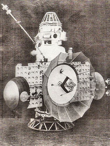
1VA (Venera-1)
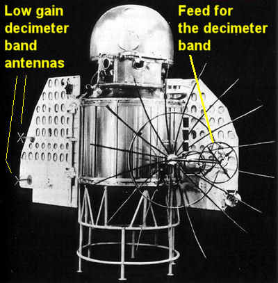
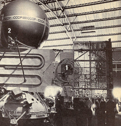
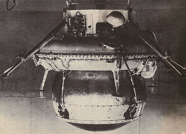
Picture 1: Venera-1, 1VA, launched on 12 February 1961 was the first successful vehicle that used the new decimeter.band radio systems. The news agency TASS announced the transmission frequency as 922.8 MHz. The rather detailed pictures of the craft that were released show no sins of antennas for any other frequency band, i.e. the 32/39 cm down/uplink system (922.8/769 MHz). The photo above shows two tunrstile antennas for the decimeter band an the high-gain paraboloc dish for the same frequecy band. All antennas were mounted on the shadow side of the spacecraft - the side of the craft was normally turned in the general direction of Earth. The fact that no cm-band transmitters were carried on the 1VA probe can probably be explained by the fact that no image transmissions requiring high bandwidth were planned for these early probes.
2MV-1 (25 August, 1 September 1962 failures)
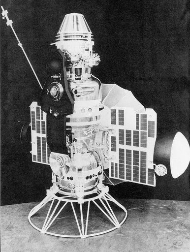
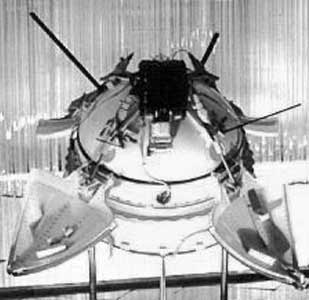
Picture
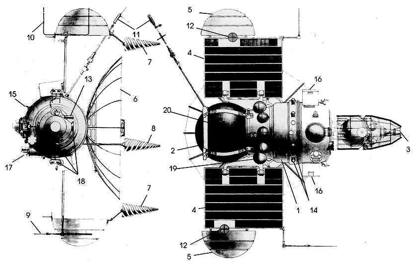
2: Venus probes (2MV-1)
unsuccessfully launched in August and September 1962.
The antenna configuration show antennas
for the metre and decimneter links. Presumably the cm link were served by
the parabolic dish. The conical helices are not used for the 2MV-4
(Mars-1) craft where the hemispherical spiral antennas were used
instead.
7 - low-gain antenna. 8 - antenna for monitoring the landing capsule. 9 - transmit antenna for the meter band. 10 - reception antenna for the meter band. 11 - omni antenna for emergency radio link. 12 - antenna for the surface section.
2MV-4 (Mars-1)
|
|
|
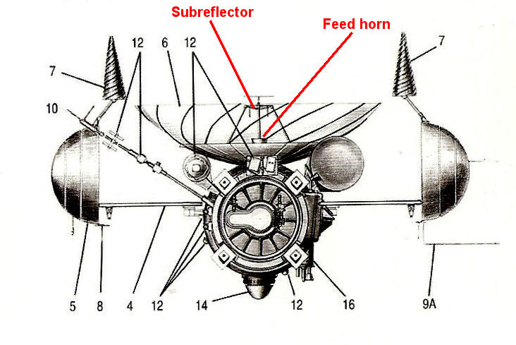
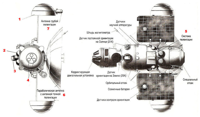
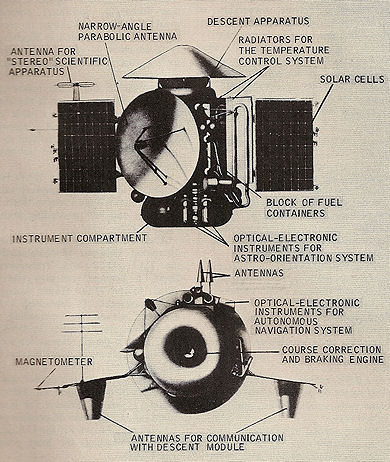
Picture 5: The antenna
configuration contains antennas for the metre and decimeter links.
Presumably the cm link were served
by the parabolic dish. I have added arrows showing
what I think are the Cassegrain feed and subreflector for the cm band
links.
The conical helices are not the those used in
flight where the hemispherical spiral antennas (Picture 4) were used
instead.
6 - high-gain parabolic antenna. 7 - low-gain
antenna. 8 - low-gain antenna. 9A - reception antenna for the meter
band.
10-omni antenna for emergency radio
link.
3MV-1 (Zond-1)
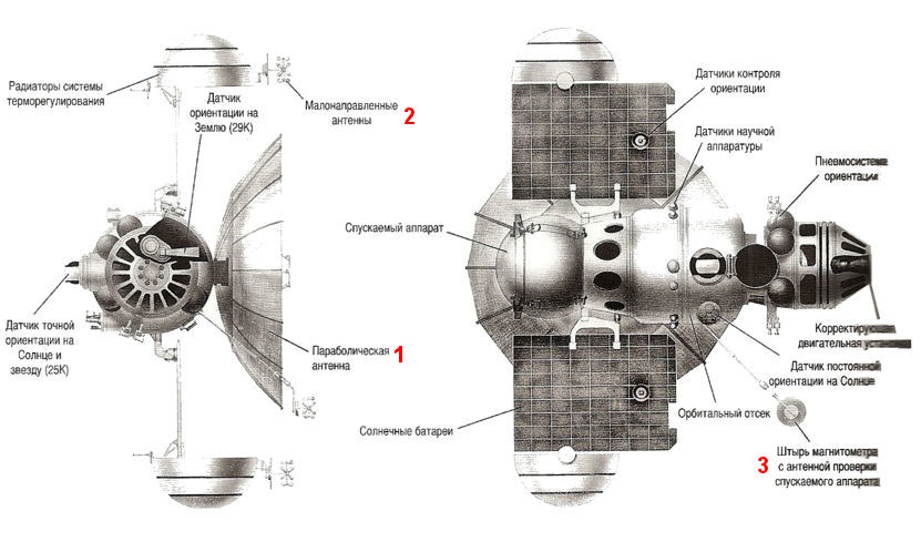
Picture 6: 1 - parabolic antenna, 2 - low-gain
antenna, 3 - boom for holding a magnetometer and an antenna for monitoring the
descent vehicle.
|
|
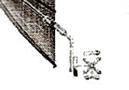
 Picture 8: Picture of Venus probe boom-mounted antenna taken by myself at the Energia Musuem in Moscow. This clearly looks like the antenna in Picture 7. It also clearly is a Lindenblad antenna. It is probably intended for the decimeter band. |
3MV-2 (Venera-2)
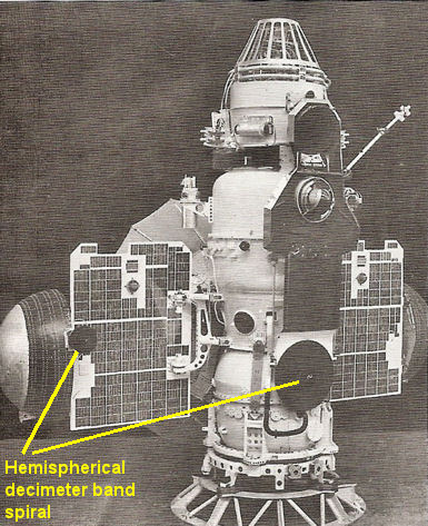
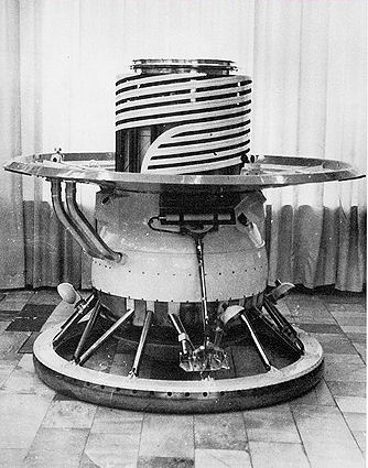
Picture 9: On the sun side of the spacecraft we can see two hemispherical spiral antennas (see Picture 4) - one on the main body of the spacecraft and one on the right thermal radiator, However, the picture shows the science module with cameras and other sensors for observing the surface of Venus. The mounting interface to the main spacecrfat is the same as for the descent capsules.
3MV-3 (Venera-3)
|
|
|
3MV-4A(Zond-2 & 3)
Picture 12: 1 - thermal control radiator, 2
- low-gain antenna (of the type shown in Picture 4), 3 - sun sensor, 4
- planet sensors and camera apertures,
5 - direction-finding system, 6 - parabolic antenna also used
for precise diretcion-finding, 7 - antenna for rough
direction-finding.
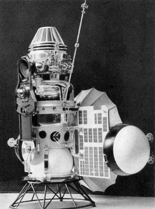
Picture 13: The photograph above supposedly shows Venera-2, but it looks more like Zond-2. The two hemispherical spiral anrennas are not grouped together as in Picture . One is on the main body and one on the tip of a solar panel. The solar cell layout looks different. However, the sketch and the picture above show clearly the science module with cameras and other sensors for observing the surface of Mars (and the Moon in the case of Zond-3). The mounting interface to the main spacecraft is the same as for the descent capsules.
![]()
Picture 14: With Venera-4 the hemispherical thermal radiotors are gone and replaced by the parabolic dish as a radiator. This works because the dish for Venus the dish always points away from the Sun. Don Mitchell wrote (8) : "T hat was one of several things Lavochkin did when they redesigned the craft.Lavochkin also favored the conical helical antennas."One can note that the two helices are slightly different. The left helix has a sharp point and the right helix is truncated. Presumably the two antennas therefore have different radiation patterns. The helices and the main parabolic antenna (here shown in stowed condition) are placed on the shadow side of the spacecraft. This side is normally turmed toward Earth because the spacecraft is intended to travel to Venus which is closer to the Sun than Earth.
4V (Venera-9 to 14)
 |
 |
In the picture on the left we can see the antennas on the main spacecraft: 1 - helix for the VHF link with the lander. 2 - conical helox for the decimeter band link. In the picture of the lander on the right we can see the unusual VHF helix on top.
M71. M73
The picture below shows the overall antenna arrangement for the second generation Mars probes.The antennas for communicating with the lander is slightly different than for the Venera probe. Here the helix is conical. This probably has to do with a different link geometry between the main spacecraft and the lander.
The picture below shows the offcial sketch of the lander where the antenna for the link to the orbiter during descent is just a whip.
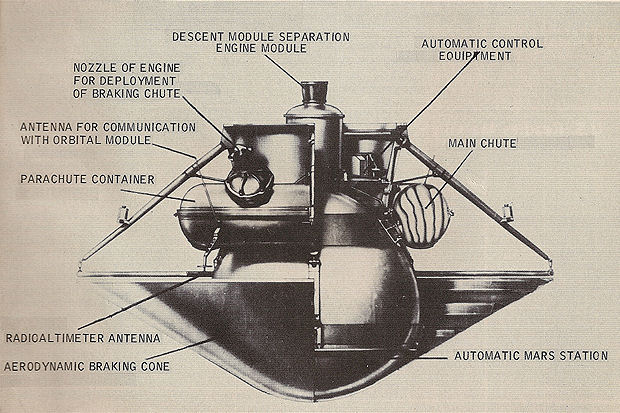
In the photo below, where the re-entry braking cone is reoved it is easy to see the atennas for the landing radar.
The not-so-good picture of the actual lander shows whip antennas for the VHF link to the orbiter.
Don Mitchell's site on the exploration of Venus and other topics.