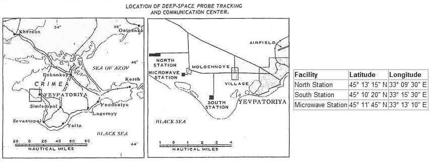
The report divides the facility into three stations: the North Station, the South Station and a Microwave station. The locations of these three sites are given on a map in the report and in numerical form.
The report contain sketches of the layout of the north and south stations as well as satellite images of the same areas. At the north station the report shows the location of the two ADU-100 antenna arrays with eight 16-meter dishes. The two arrays are 600 meters apart according to the report these are probably the transmitting antennas for communicating with space probes. The support area of the station is said to contain some 27 buildings as well as a suspected short-wave radio antenna area.
The South Station has one 8-dish array (see below) and a "semiburied control building". The report speculates that this the transmitter site for deep-space communications. The microwave station is equipped with a 72 meter high tower with two microwave dishes pointing in the general area of Simferopol. A wire line connects the the microwave station to the North Station.
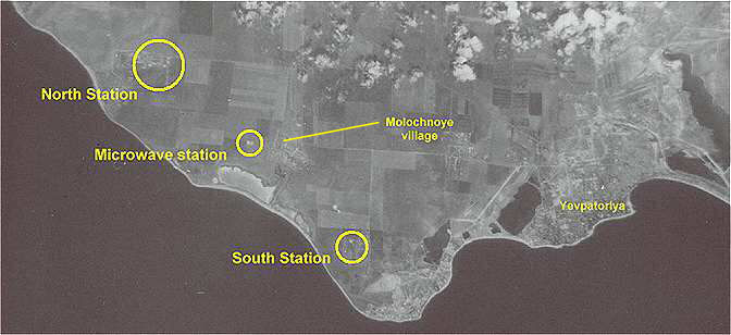
The three stations can be seen in this and other shots from the KH-4A Mission 1047-2 in June 1968. The KH-4A resolution is limited but its enough to make things out but the details in the report probably came from some other means. The satellite images shown below have been obtained from The National Archives by Charles P Vick and converted to digital form by him.
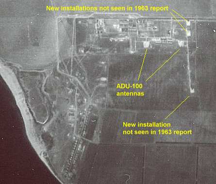
The layout of the north station can also be seen in a satellite picture taken in the late 60's. The ADU-100 dishes are still there, but there are some new installations also.
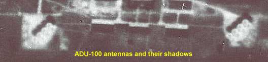
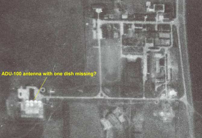
A blow-up of the area of the two ADU-100 antennas shows them and their shadows clearly.
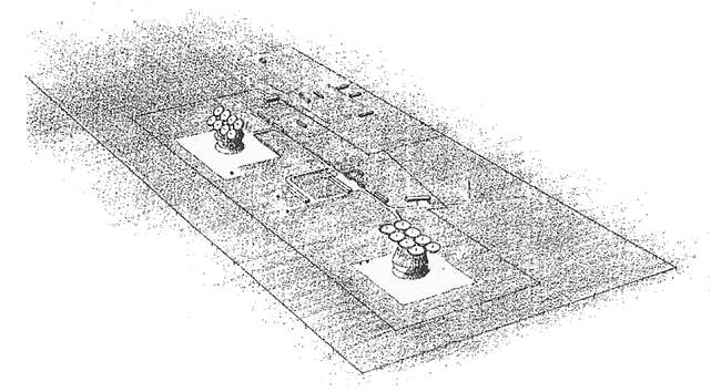
In the NPIC report from 1963 an artist's view of the two ADU-100 antennas is provided.
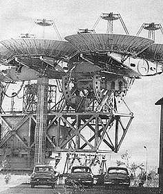
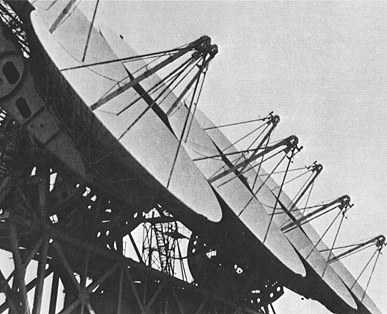
There are photos of these two antennas, showing them to be double reflector dishes as in the picture below. This is an important fact to note because the South Station is probably equipped with a slightly different antenna design (see below).
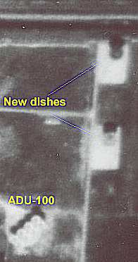
The three distinctly new facilities mentioned earlier look like very big dishes. Two of the new installations near the eastern ADU100 are shown below. Perhaps these are the new "Saturn" antennas installed at the mid-to-end 60's.
The satellite picture of the south station below shows an interesting detail! Can you see more than seven dishes in the array?
There is a picture of an antenna with a completely different front feed system for the dishes. The usual pictures of the system show a Cassegrain system with subreflectors mounted on quadrapods in front of the dishes (see "North Station"). In the unusual picture (see below) there is a "shepherd's hook" waveguide which seems to be about 29-30 cm wide, i.e. about 11 inches which means that it could well be intended for the standard 770 MHz deep-space uplink! It seems reasonable to assume that this is the transmit antenna at the the "South station". Thus, it seems safe to assume that the double reflector antennas are those for reception at the "North Station".
South station transmit antenna?
They were probably intended
mostly for the the UHF and microwave frequencies
of Soviet deep-space probes and spacecraft in the manned lunar program.
The deep-space probes, starting with the first Venus and Mars probes in
1961-62, used the following downlink frequencies:
Zond spacecraft designed for manned circumnavigation of the Moon used the 922.76 MHz/768.96 MHz system and probably also the 183.6 MHz downlink (see separate article). In all probability the N-1/L3 manned lunar landing system was intended to use these frequency bands also. |