The radio systems of the early Luna
probes
Sven Grahn
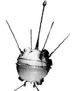 The early lunar probes launched by the Soviet Union (Luna
1-3)
carried rather simple radio systems. This article is a description of these
systems
and how they worked, as well as can be determined so long after the
actual
events. In general the probes carried
The early lunar probes launched by the Soviet Union (Luna
1-3)
carried rather simple radio systems. This article is a description of these
systems
and how they worked, as well as can be determined so long after the
actual
events. In general the probes carried
-
a main radio system for telemetry, tracking and command (only Luna-3 had
a command link) working
on VHF
and with a 9/5 turnaround ratio (RTS-12B).
-
simple HF transmitters with
FSK
or on-off keying for some scientific data (Jupiter).
-
at least for the first
two Luna
probes the last stage of the carrier rocket had HF transmitters sending
science data from a package in the stage.
-
the last stage of the rocket
also
carried an S-band transponder (Fakel-S) for trajectory determination during
powered flight.
-
the last stage also had VHF
telemetry systems
(RTS-8E, RTS-12A) for use during powered flight.
The S-band radar tracking provided
an
initial estimate of the state vector and the subsequent trajectory, which
was then updated by ranging measurements made through the VHF ranging
link
(RTS-12B).
Post-Cold War account of Luna
1-3 radio systems
This account is based on
information from (12), "Unforgettable
Baikonur". The table below summarizes the information in that
document.
| Vehicle |
Radio system |
Phase |
Pre- December
1958
launch |
Luna-1 |
Luna-2 |
Luna-3 |
| Probe |
Jupiter-1 |
Cruise |
- |
19.993 MHz |
19.993 MHz |
- |
| |
Jupiter-2 |
Cruise |
- |
- |
39.986 MHz |
39.986 MHz |
| |
RTS-12B down |
Cruise |
183.6 MHz |
183.6 MHz |
183.6 MHz |
183.6 MHz |
| |
RTS-12B up |
Cruise |
102 MHz |
102 MHz |
102 MHz |
102 MHz |
| 3rd stage |
? |
Cruise |
19.995 MHz |
19.995
MHz |
19.997
MHz |
? |
| |
? |
Cruise |
19.997 MHz |
19.997
MHz |
20.003 MHz |
? |
| |
RTS-8E |
Launch |
183.6 MHz |
183.6
MHz |
- |
- |
| |
RTS-12A |
Launch |
- |
- |
182.0 MHz |
182.0 MHz |
| |
Fakel-S |
Launch |
2.7-2.8
GHz |
2.7-2.8 GHz |
2.7-2.8 GHz |
2.7-2.8 GHz |
The RTS-12B system on 183.6 MHz
for flights up to and including Luna-2
The RTS-12B
system for probes up to Luna-1 had
a complex pulse-position modulation system, where the frequency shift
pulses of the velocity vector system with the period 0.5 second were somehow transmitted
together with the short (10 milliseconds) pulses of the pulse-position modulation
(PPM) telemetry (15
). A complete telemetry frame contained 120
measuring channels and was transmitted in 2 minutes, i.e. one interrogation, or
"data word", per second. The frame marker consisted of three pulses.
It is unclear how the telemetry pulses were modulated on the carrier.
The "velocity vector" frequency shift pulses are given as 0.5 seconds
long. It is unclear if this
is the rise time or the total back-and-forth pulse time. Interestingly, the
"velocity vector" system worked well on Luna-1, but the
telemetry modulation in the RTS-12B system did not work on that flight.
For Luna-2 the
flight the RTS-12B system was changed so that the ranging system and telemetry
system did not work at the same time, but rather in turn. Also the telemetry
part of the system used the same modulation as the Jupiter system - i.e. PDM
(Pulse-Duration Modulation). A narrow-band filter had to be added to the RTS-12B
ground receiver to make up for the fact that a keyed carrier was used for
telemetry. The ranging system worked by bursts of pulses with short-term change
in the carrier frequency.
 The "Jupiter" systems on 20 and
40 MHz
The "Jupiter" systems on 20 and
40 MHz
The RTS-12B was evidently
causing problems in the early phase of the program, so on the third launch
in December 1958 (which failed) the "Jupiter-1" system was added.
That uses two long ribbon antennas on the space probe. It
replicated the same telemetry information as was carried by the RTS-12B system
on a frequency of 20 MHz. Just as with the RTS-12B system 120 parameters
were transmitted in a 2 minute cycle. So, the "Jupiter-1"
system added in late 1958 saved the scientific mission of Luna-1 in which the
RTS-12B system on VHF failed.
For Luna-2 a second low-frequency telemetry
system, "Jupiter-2", operating near 40 MHz, was added. The transmitter Jupiter-2 worked
in the pauses of transmitter Jupiter-1 (by opposite coding, transferring
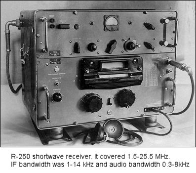
the same information).The receiving system for Jupiter at Baikonur
consisted of two troop receivers of R-250 type (see image on right. Thanks to
Don P Mitchell for the picture).Recording of information was conducted by tape recorders
and photoregistering equipment common with the RTS-12B station.
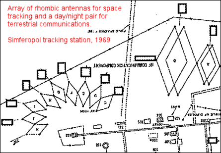
An antenna field
of five rhombic shortwave antennas were erected on wooden posts
and were used for both "Jupiter-1" and "Jupiter-2".These wire antennas extended a sector of 150° in azimuth
with the center axis to the south. The antennas were switched by hand as the
spacecraft moved from the east to the west. In (14) the layout of a
rhombic array at the Simferopol
tracking station is shown (see image below right). A fan-shaped array of nine
rhombic antennas are indicated as being used for space tracking. A pair of
rhombic antennas of different size is indicated as being a "day/night
pair" for terrestrial communications, most probably with Moscow. The rhombic antennas
at Baikonur were modified in
1960 to be bidirectional. This provided around-the horizon coverage. the same is probably
true for the Simferopol array. In 1959 the Baikonur rhombic array
only had coverage to the south where the Luna probes traversed the sky. The modification
of the Baikonur array in 1960 was done to support the shortwave "Signal" beacon on
the space vehicles in the Vostok program, the first test vehicle
of which was launched on 15 May 1960.
 Luna-3 only supported by Simeiz and far east station in
Yelizovo
Luna-3 only supported by Simeiz and far east station in
Yelizovo
For Luna-3, the spacecraft that took pictures of the far
side of the moon, a new radio system had been developed by NII-885 under the
management of Yevgeni Boguslavsky (13
). The system transmitted the images of the
moon, relayed telemetry, measured the range and range rate, and received commands from the
ground and acknowledged the reception of these commands. The "Jupiter-1" system was deleted and only the "Jupiter-2" system was
retained.
During the flights of Luna-1 and Luna-2
data reception was performed at Baikonur and the temporary tracking station at Simeiz
in the Crimea. During the flight of Luna-3 no reception of signals out
to lunar distances was made at Baikonur - only out to 40000 km. Only
the stations at Simeiz and Yelizovo on the Kamchatka peninsula communicated with Luna-3 far away from the
earth.
RTS-8E system on 183.6 MHz on the carrier rocket
used up to and including Luna-1
The RTS-8E system had a pulse-position-modulated radio
transmitter with a 100 W pulse power. It carried 26 measuring channels
on 100 interrogations per second (one data word every 10 milliseconds). Each
measurement "word" consisted of a reference pulse (7 microseconds long) and
a measuring pulse (4 microseconds long). There were 3 additional
channels for the calibration. Frame synchronisation was provided by a pause
approximately 1000 microseconds (1 millisecond)? The RTS-8E system was a modification of RTS-8, which was
developed in 1956 to test the R-7 missile, but lost the design competition to the Tral
system.
RTS-12A system on 182.0 MHz on the carrier
rocket used on Luna-2 and Luna-3
This system was a very slight modification of
the RTS-8E brought about my lowering the transmission frequency to avoid any
risk of interference with the RTS-12B probe transmitter on 183.6 MHz. The
RTS-12A adopted the frequency 182.0
MHz
Sergei Korolev
writes about the subject
In a document written in
early
1958 (9) Sergei Korolev described plans for the early
Luna probes:
...."The radio system operates in the
wavelength
range 1.6 - 2.5 m. The range from the earth to the spacecraft is
measured
by an active radar. The pulse signal of the range determination is
re-sent
as a range signal and used on the earth to measure the range from the
earth
to the spacecraft. From the distance 20.000 - 30.000 km to the Moon,
the
range from the spacecraft to the Moon starts to be measured
simultaneously
with the measurements the earth - spacecraft distance. Beside the pulse
signals, the on-board radio transmitter sends to the earth a continuous
signal with a power of the order of 10 W to determine the spacecraft
velocity.
This results in the signal power on the earth of the order of 0.1
microwatts
only. Receiving such a signal will be made by radio astronomy dishes in
Simeiz". .....
Simeiz
is a small city near Yevpatoria in the Crimea. In all probability Korolev
describes the ranging system operating on approx 102 MHz uplink (probably
equivalent to the uplink 101.965 MHz used for Luna-16, 20...) and 183.6 MHz
downlink (see
Luna 1
or
Luna 2 below). The translation of
Korolev's text was provided by Dr Stas Barabash, Swedish Institute of Space
Physics, Kiruna.
In the Energiya history
book
(11)
the control center for the lunar missions is described as temporary and
set up on the Koshka mountain near the city of Simeiz and using the
facilities
of the Crimean Observatory and the Physical Institute of the USSR
Academy
of Sciences. In (11) it is also
indicated
that the radio systems of the early Luna probes were developed by
NII-885
under the leadership of Mikhail S. Ryazanskiy, Chief Designer of Radio
Control Systems.
Details of Luna 1-3 radio systems in TASS announcements and
foreign tracking reports
Luna 1
- In (2)
the last stage of the carrier rocket is said to have carried a radio transmitter operating
on two frequencies, 19.997 and 19.995 MHz telegraphic transmissions
with
0.8 and 1.6 seconds duration. This transmitter was used to report
data
from a cosmic radiation counter.
-
The only
known,
but unconfirmed, reception report of the signal on 19.997 MHz is
described
in (1)
. The signal consisted of four pulses
lasting
1.6 seconds every 10 seconds.
-
According to (2) the last stage
was
also equipped with a radar transponder. The radar transponder is the
S-band
(2700-2900 MHz) system mentioned above.
-
According to (2)the
probe was equipped
with a radio transmitter operating on the frequency 19.993 MHz with
telegraphic transmissions with varying duration of 0.5-0.9 seconds with which
scientific instrument readings were transmitted.
-
The probe also had a telemetry transmitter operating on 183.6 MHz
which also carried "trajectory measurement". Additionally, the probe
carried
a receiver for ranging signals from the ground. This probably
operated on 102 MHz (see discussion of
radio
systems on Luna 20 return craft
).
-
JPL director W Pickering said (4) that
the telemetry on 183.6 MHz was FSK at 5 Hz keying rate and changing a few kHz
in frequency. Recordings released by Moscow showed the repetition rate nearer
1 Hz. JPL picked up the signal from Luna 1 after the probe had passed the
Moon.
Luna 2
- The last stage of the
carrier
rocket was equipped with radio systems analogous to those on Luna
1.
According to (2) the radio transmitter operated on two
frequencies, 20.003 and 19.997 MHz sending telegraphic transmissions varying
in length between 0.8 and 1.5 seconds duration. When there was a pause on one
frequency the signals was transmitted on the other frequency.
-
In (2) a telemetry system in the
probe
operating on 19.993 and 39.986 MHz is described. The signals consisted
of pulses 0.2-0.8 seconds long sent at a repetition rate of 1 +/- 0.15
Hz."Length of and interval between telegraph pulses transmit essential
scientific information". In (3) it is said that the signals on the two
frequencies are generated from common crystal-controlled oscillator operated
in "telegraph mode" (i.e. on-off). A break in transmission from either one
initiated transmission from the other. This system is identical in principle
to the system used on Sputnik 1 to transmit pressure and temperature inside
the satellite.The same method was also used on the Voskhod series to
transmit cosmonaut pulse
rate and respiration
.
- On-off
telemetry like the signal on 19.993 MHz was also transmitted from the
probe
on 183.6 MHz according to (5) and this
transmitter
also carried "trajectory measurements" (2). The trajectory
measurements were probably the
frequency-shift ranging
later observed
by me to be used on the Luna 20. I found a fascinating description of this
trajectory measuring system in
account by
L.I Gusev
, the director of NII-85 (now known as
RNIIKP).
Luna 3
- No radio systems have been
described
for the last stage of the carrier rocket, although it was
indicated
in TASS statements (2) that it carried 156.5 kg of scientific
instruments.
-
Interestingly the probe no longer
was equipped with shortwave transmitters near 20 MHz, but only with a
transmitter
on 39.986 MHz transmitting pulses 0.2-0.8 seconds long sent at a
repetition
rate of 1 +/- 0.15 Hz.(2).
- According to (10) the picture
transmissions from the probe were frequency-modulated on 183.6 MHz which also
carried "trajectory measurements". In (5
) the modulation is
described as "frequency shift modulation".
-
In
(7) signals from Luna 3 are described as "15
sec on 15 sec off (probably the off period represents a frequency shift).
There are two signals in the band with about 5 kHz separation." This is a
description that suggests signals like the
"frequency sweeps" that I received from Luna 20
.
- In the Jodrell
Bank
Archives the signals received on 183.6 MHz from Luna 3 are described in
various communications and the descriptions do not contradict the frequency-sweep ranging
hypothesis.
In one telegram Jodrell bank states "CW at one of several frequencies
near
183.6 MHz". "...SIGNALS HAVE BEEN RECEIVED ON SEVERAL CHANNELS IN
FREQUENCY
BAND 183.600 +/- .01 MHZ...."(8).
- In
another
message the VHF transmissions are simply described as "signals on
183.600
MHz +/- 0-5 kHz" (6).
Frequencies
announced in the West
Several sources have given other
frequencies for Luna-1. In Nature (19) 71.2 and
212 MHz were mentioned as frequencies for Luna-1 but without
any details.
- In the U.S. Senate hearings
about Luna-1 (4) there is a report
from Stanford University that mentions that it was alerted to the possible use
of the frequency 71.2 MHz by Lunik and that the station tried this frequency
by hooking up a six-element Yagi to a Nems-Clarke receiver.
-
In (16) it is reported that the USAF station at
Hilo, Hawaii picked up signals on 70.2 MHz (not 71.2 -
misprint?) 15-20 minutes after launch and that other USAF stations also picked
up 70.2 MHz and 212 MHz. These stations were Singapore, Millstone Hill (Mass.,
USA) and Cape Canaveral.
It is entirely believable that
there were signals on these frequencies and that at least Hawaii got them. On
the last stage of the A-2 (Vostok-type in Soviet parlance) vehicle there are
hairpin shaped antennas very well matching the two frequencies. It is doubtful
if these signals could be heard very far out from Earth since they were probably
rather broadband containing high speed telemetry from many sensors associated
with the propulsion system in the last stage. Also, the batteries for these
transmitters probably went dead quickly.
But why are not these frequencies mentioned in (12) which reveals so much previously
secret information? And where does this frequency information in Nature come
from ? An unintentional leak from Jodrell
Bank?
References
-
"Simplified
Tracking Gear Provides Much Data", Missiles and Rockets, March 16,
1959,
pp. 29-33.
-
Mastery
of Cosmic Space by the USSR, official TASS communiques and materials
from
the central press 1957-1967, Nauka Publishers, Moscow 1971.
-
V.A.
Kotelnikov, .M. Dubrovin, O.N. Rzhiga and A.M. Shakhovsky.
"Reception
and investigation of the properties of radio signals from Soviet Space
Rockets".
-
Hearings
before the Committee on Science and Astronautics and Special
Subcommittee
on Lunik Probe, U.S. House of Representatitives, Eighty-Sixth Congress,
First Session, U.S. Governement Printing Office, Washington D.C., 1959.
The hearings were held during the period May 11-29, 1959.
-
J.G
Davies, A.C.B. Lovell, Observations of the Russian Moon Rockets
Lunik
II and III, Space Research 1, Proceedings of the first COSPAR
conference,
1960.
-
A
telegram
from Jodrell Bank to SPACE CONN NASA WASH DC dated 4 October 1959
-
A
telegram
from Jodrell Bank to SPACE CONN NASA WASH DC dated 7 October 1959
-
A
telegram
sent by Prof. J.B Davies at Jodrell Bank to MEGER, PRAHA on 15 October
1959 describing signal from Luna 3.
-
S.P
Korolev (edited by M Keldysh), "The Creative Legacy of Academician
S.P. Korolev", Nauka, Moscow 1980, p.402.
-
V.Ye
Demidov, "Radio Bridge- 'Earth-Moon-Earth'." Znaniye Press, Moscow
1967.
-
Yu.
P Semenov, ed. Raketno-Kosmicheskaya Korporatsiya "Energiya" imeni
S.P. Koroleva 1946-1996, 1996, p. 97
- K.V.Gerchik (ed.), "Nezabyvaemy Baikonur" (Unforgettable
Baikonur), 1998.
- Deputy chief designer of the Scientific Research
Institute. of Radio Instrument Building.
- The Simferopol Space Flight
Center, National Photographic Interpretation center, June 1969, Report
RCA-03/0017/69
- Called
pulse-time modulation in (12))
- Martin
Caidin, "Race for the Moon" William Kimber Publisher, London
1960.
- NATURE, January 10, 1959, page
83.

 Back to Space Radio
Notes
Back to Space Radio
Notes